Advanced Search

BSCP 75: Registration of Meter Aggregation Rules For Volume Allocation Units

v 15.0
Download Forms
Download

Balancing and Settlement Code

BSC PROCEDURE

Registration of Meter Aggregation Rules For Volume Allocation Units

BSCP75

Version 15.0

Date: 29 March 2019

BSC PROCEDURE 75 relating to REGISTRATION OF METER AGGREGATION RULES FOR VOLUME ALLOCATION UNITS

    1. Reference is made to the Balancing and Settlement Code and, in particular, to the definition of "BSC Procedure" in Section X, Annex X-1 thereof.

    2. This is BSC Procedure 75, Version 15.0 relating to Registration of Meter Aggregation Rules for Volume Allocation Units.

    3. This BSC Procedure is effective from 29 March 2019.

    4. This BSC Procedure has been approved by the Panel.

Intellectual Property Rights, Copyright and Disclaimer

The copyright and other intellectual property rights in this document are vested in ELEXON or appear with the consent of the copyright owner. These materials are made available for you for the purposes of your participation in the electricity industry. If you have an interest in the electricity industry, you may view, download, copy, distribute, modify, transmit, publish, sell or create derivative works (in whatever format) from this document or in other cases use for personal academic or other non-commercial purposes. All copyright and other proprietary notices contained in the document must be retained on any copy you make.

All other rights of the copyright owner not expressly dealt with above are reserved.

No representation, warranty or guarantee is made that the information in this document is accurate or complete. While care is taken in the collection and provision of this information, ELEXON Limited shall not be liable for any errors, omissions, misstatements or mistakes in any information or damages resulting from the use of this information or action taken in reliance on it.

AMENDMENT RECORD

VERSION

DATE

DESCRIPTION OF CHANGES

CRs INCLUDED

MODS PANEL REF

1.0

Code Effective Date

Designated version

n/a

n/a

2.0

11/30/2000

Work outstanding at Go Active resolution of inconsistencies inclusion of consultation comments

211

08/009

3.0

13/08/2002

Change Proposals for BSC Systems Release 2

CP546, 726, 781

ISG 16/166, ISG 18/193

4.0

24/06/2003

Change Proposals for the June 03 Release

CP570, CP756, CP821

5.0

01/08/2003

Approved Modification P62 and an outstanding change for P55

P62, P55

P62 48/003

6.0

30/06/2004

Change proposal for the CVA Programme June 04 Release

CP971

ISG/40/003

7.0

23/02/2005

CVA Programme Feb 05 Release

BETTA 6.3, CP1049

8.0

01/11/2007

November 07 Release

CP1197

ISG 73/02

9.0

20/04/2009

P216 Release

P216

ISG97/02

10.0

27/01/10

P240 Modification

P240

Panel

11.0

25/02/10

February 10 Release

CP1301

ISG103/01

12.0

24/06/10

June 10 Release

CP1332

ISG113/02

13.0

28/06/12

June 12 Release

CP1356

ISG130/04

CP1372

ISG136/02

14.0

28/02/19

February 2019 Release

P344

Panel 284C/01

15.0

29/03/19

March 2019 Standalone Release

P369

Panel 285/12

1 Introduction

1.1 Purpose and Scope of the Procedure

This BSCP defines the process for submission of Aggregation Rules by Parties to the Central Data Collection Agent (CDCA) for Volume Allocation Units as defined in Section R of the Code. This BSCP describes the key interfaces and timetable responsibilities for interested parties.

This procedure also defines the process for the Lead Party of Primary BM Units in a Switching Group to instruct CDCA to use a different set of Aggregation Rules (chosen from a number of pre-registered sets) to reflect the switching of Plant and Apparatus between Primary BM Units.

This procedure does not include the registration of Aggregation Rules for Supplier Primary BM Units.

The Virtual Lead Party are not required to register Aggregation Rules for Secondary BM Units.

1.2 Main Users of the Procedure and their Responsibilities

This BSCP should be used by the following:

(a) Party for the submission of Aggregation Rules

(b) CDCA for validating and registering the Aggregation Rules

Throughout this procedure, timetables reflect the number of Working Days (WD) following defined events by which an activity should be completed.

1.3 Key Milestones

Timescales for the registration of Aggregation Rules can be reduced upon agreement between all relevant parties. Other key milestones in this procedure are:

    • 20 WD notice for submission of Aggregation Rules

    • Selection of Aggregation Rules for Range CCGT Modules with the same timescales as defined in the Grid Code

    • Selection of Aggregation Rules for Primary BM Units in Switching Groups within 2 WD of operational switching

1.4 Balancing and Settlement Code Provision

This BSCP should be read in conjunction with the Code and in particular Section K and Section R.

This BSCP has been produced in accordance with the provisions of the Code. In the event of an inconsistency between the provisions of this BSCP and the Code, the provisions of the Code shall prevail.

1.5 Associated BSC Procedures

This procedure interfaces with the following BSCPs:

BSCP15

BM Unit Registration

BSCP20

Registration of Metering System for Central Volume Allocation

BSCP25

Registration of Transmission System Boundary Points, Grid Supply Points, GSP Groups and Distribution Systems Connection Points

BSCP38

Authorisations

BSCP128

Production, Submission, Audit and Approval of Line Loss Factors

BSCP515

Licensed Distribution

1.6 Other

Typical examples concerning Primary BM Unit configurations and guidance for Aggregation Rules can be found in section 4.1.

2 Acronyms and Definitions

2.1 List of Acronyms

The following is a list of acronyms used in BSCP75:

AE

Active Export

AI

Active Import

CDCA

Central Data Collection Agent

CRA

Central Registration Agent

CRS

Central Registration System

CST

Constant

CVA

Central Volume Allocation

DSCP

Distribution System Connection Point

ER

Expression Reference

FPN

Final Physical Notification

GSP

Grid Supply Point

LDSO

Licensed Distribution System Operator

LLF

Line Loss Factor

MSQ

Metering Subsystem Quantity

NETSO

National Electricity Transmission System Operator as the holder of the Transmission Licence and any reference to “NETSO”, “NGESO”, “National Grid Company” or “NGC” in the Code or any Subsidiary Document shall have the same meaning.

SMRS

Supplier Meter Registration Service

SVA

Supplier Volume Allocation

WD

Working Day

2.2 List of Definitions

Full definitions of the above acronyms in Section 2.1 are included in the Code.

CVA registered Primary BM Unit / Volume Allocation Unit

A Primary BM Unit or Volume Allocation Unit comprising Plant and/or Apparatus whose Imports and Exports are measured by CVA Metering Systems.

Effective From Date

The Settlement Day from which the Aggregation Rules will become active.

Nominated Licensed Distribution System Operator

The Nominated LDSO is the LDSO who has obligations to submit the GSP Group Metered Volume Aggregation Rules. For the avoidance of doubt, the Nominated LDSO is the LDSO who was responsible for each GSP Group on 01 August 2003 or the Scottish Distribution Licensee in respect of that Bulk Supply Point Group under the Settlement Agreement for Scotland on 1 August 2003.

Contracted Licensed Distribution System Operator

The LDSO who provides the SMRS to the Registrant of the Metering System.

SVA registered Primary BM Unit

A Supplier Primary BM Unit.

3 Interface and Timetable Information

3.1 Registration of Aggregation Rules

REF

WHEN

ACTION

FROM

TO

INFORMATION REQUIRED

METHOD

3.1.1

At least 20 WD prior to the Effective From Date

Submit Aggregation Rules for Volume Allocation Unit. (Examples of completing Form BSCP75/4.2 can be found in Section 4.3).

Party

CDCA

Form BSCP75/4.2 Registration of Aggregation Rules for Volume Allocation Unit.

(CDCA-I001 Aggregation Rules)

Fax / Letter/ Email

3.1.2

Within 1 WD of receipt of data from 3.1.1

The CDCA shall acknowledge receipt of the Aggregation Rules.

CDCA

Party

Form BSCP75/4.2 Registration of Aggregation Rules for Volume Allocation Unit.

Fax / Letter / Email

3.1.3

Within 1 WD of receipt of data from 3.1.1

The CDCA shall validate the Aggregation Rules including:

  • Completeness and Authorisation

  • The appropriate Metering System(s) is registered on or before the Effective From Date

CDCA

Form BSCP75/4.2 Registration of Aggregation Rules for Volume Allocation Unit.

BSCP38 Authorisations.

Internal

3.1.4

Within 2 WD of receipt of data from 3.1.1 and if supporting information required

Request supporting information.

CDCA

Party

Additional information (including but not limited to network diagrams, connection agreements and installation documentation).

Fax / Letter/ Email

3.1.5

Within 3 WD of request for supporting information

Provide supporting information requested in 3.1.4.

Party

CDCA

Supporting information as requested.

Fax / Letter/ Email

3.1.6

Within 1 WD of receipt of information from 3.1.5

The CDCA shall re-validate the Aggregation Rules.

CDCA

Supporting information.

Internal

3.1.7

Within 1 WD of 3.1.3 or 3.1.6 and if Aggregation Rules fail validation

Inform Party (detailing the reasons for the failure) and request Party to re-submit a new set of Aggregation Rules.

Return to 3.1.1.

CDCA

Party

Reasons for failure and request Party to re-submit Aggregation Rules.

Fax / Letter/ Email

3.1.8

Following 3.1.3 or 3.1.6 and if the Aggregation Rules have been successfully validated

Where the Aggregation Rules are for a CVA registered Primary BM Unit, associated with embedded Plant or Apparatus, or new GSP the CDCA will request that the Nominated LDSO provide revised GSP Group Metered Volume Aggregation Rules.

CDCA

Nominated LDSO

Revised GSP Group Metered Volume Aggregation Rules.

Fax/Letter/ Email

3.1.9

Following 3.1.8 and within 5 WD of successful validation

Provide revised GSP Group Metered Volume Aggregation Rules.

Nominated LDSO

CDCA

Revised GSP Group Metered Volume Aggregation Rules.

3.1.10

Following 3.1.9 and within 5 WD of successful validation

The CDCA shall re-calculate the Aggregation Rules for the relevant GSP Group Take.

CDCA

Internal

3.1.11

Following 3.1.10 and within 5 WD of successful validation

Provide re-calculated GSP Group Take Aggregation Rules.

CDCA

Nominated LDSO

Re-calculated GSP Group Take Aggregation Rules.

Fax/Letter/ Email

3.1.12

Following 3.1.11 and within 5 WD of successful validation

Agree GSP Group Take Aggregation Rules with Contracted LDSOs.

Nominated LDSO

Contracted LDSO(s)

Agreement of the GSP Group Take Aggregation Rules.

3.1.13

Following 3.1.12 and within 5 WD of successful validation

Confirm to the CDCA that the GSP Group Aggregation Rules are accurate.

Nominated LDSO

CDCA

Confirmation of the GSP Group Take Aggregation Rules.

Fax/Letter/ Email

3.1.14

Prior to Effective From Date

Produce confirmation report of aggregation rule data entered into system and provide to Party to confirm.

CDCA

Party

Aggregation rule report confirmation of data entered into systems.

CDCA-I048 Report of Aggregation Rules

Fax / Letter/ Email

3.1.15

Prior to Effective From Date

Provide copy of the GSP Group Take Aggregation Rules to LDSO

CDCA

Nominated LDSO

Standing data reports prints of data entered into systems.

Fax / Letter/ Email

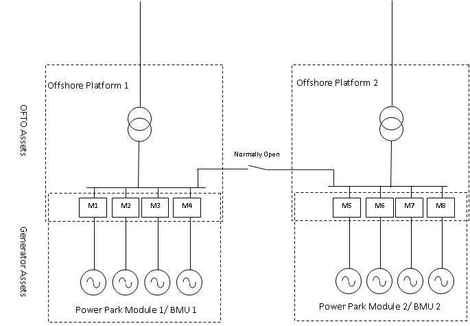
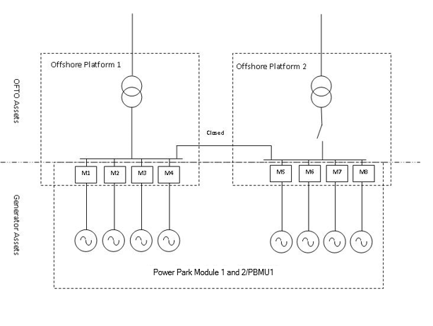
3.2 Notification of Operational Switching1

REF

WHEN

ACTION

FROM

TO

INFORMATION REQUIRED

METHOD

3.2.1

Within 2 WD of switching of Plant and Apparatus between Primary BM Units in a GSP Group (if that switching requires different Aggregation Rules)

Submit form2 electing which of the pre‑registered sets of Aggregation Rules is now applicable.

Party

CDCA

Form BSCP75/4.4 Election of Pre-Registered Aggregation Rule for Switching Group

Fax / Letter/ Email

3.2.2

Within 1 WD of receipt of 3.2.1

The CDCA shall validate that set of Aggregation Rules identified on the BSCP75/4.4 form has previously been registered in accordance with 3.1.

CDCA

Internal

3.2.3

Within 1 WD of receipt of 3.2.1 and if form fails validation

Inform Party that the required configuration has not been pre-registered

CDCA

Party

Fax / Letter/ Email

3.2.4

Within 5 WD of receipt of 3.2.1 and if form passes validation

Configure CDCA system to use selected Aggregation Rules effective from midnight following the time of switching specified on the BSCP75/4.4 form

CDCA

Internal

3.2.5

Within 1 WD of 3.2.4.

Produce confirmation report of aggregation rule data entered into system and provide to Party to confirm.

CDCA

Party

Aggregation rule report confirmation of data entered into systems.

CDCA-I048 Report of Aggregation Rules

Fax / Letter/ Email

4 Appendices

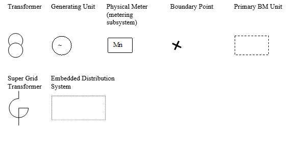
4.1 Typical Configurations and Aggregation Rules for Volume Allocation Units

4.1.1 Overview

In order to calculate the Metered Volume for a Volume Allocation Unit, Aggregation Rules have to be submitted by Parties to enable metered data values to be aggregated to the appropriate Metered Volume. The responsibilities are detailed in Section R of the Code. This means that Parties have an obligation to register Aggregation Rules with the CDCA for the following Volume Allocation Units in accordance with this BSCP (the Volume Allocation Units themselves are registered with the CRA):

    • Primary BM Units (other than Interconnector Primary BM Units and Supplier Primary BM Units)

    • Grid Supply Points

    • GSP Groups

    • Interconnectors

Listed below are examples of the typical configurations of the four Volume Allocation Units that require Aggregation Rules to be submitted. Aggregation Rules are submitted using the Metering System ID and metering subsystem ID and, where appropriate, Primary BM Unit ID, GSP ID, GSP Group ID and Interconnector ID.

The identifier for a specific flow consists of the Metering System ID, the metering subsystem ID and the measurement quantity.

    • The Custom and practice is that Export Meters are used to measure flows from Plant or Apparatus and Import Meters are used to measure flows to Plant or Apparatus.

    • Any flow on an Export Meter is classified as AE. Any flow on an Import Meter is classified as AI.

    • In all cases, a net flow measured by a metering subsystem will be calculated as [AE-AI]. Hence, a net flow from Plant/Apparatus will be treated as positive and a net flow to Plant/Apparatus will be treated as negative. Therefore the Volume Allocation Unit which has a net Import will be treated as negative and a Volume Allocation Unit which has a net Export will be treated as positive.

    • All net flows measured by a metering subsystem which are to be accounted for in a given Volume Allocation Unit will be summed. This will give an overall net flow into or out of the given Volume Allocation Unit.

    • All net flows measured by a metering subsystem which are to be accounted for in any other Volume Allocation Units that are associated with the given Volume Allocation Unit should be subtracted from the above summated net flow. The outcome of the above two operations will be the net flow for the given Volume Allocation Unit.

In the case of GSP Group Takes, a further set of net flows need to be subtracted from the summated net flows derived in the above steps. These are the net flows measured by metering subsystems of CVA registered Volume Allocation Units which are embedded within the GSP Group. The prime responsibility for identifying these CVA registered Volume Allocation Units lies with the CDCA (rather than with Parties). However, the CDCA will fulfil this responsibility by requesting LDSOs to submit Aggregation Rules for GSP Group Take for their authorised area and the LDSOs shall comply with any such request.

In the illustrations that follow the above logic is used. However, the diagrams show metering subsystems, rather than individual meters, registers or channels.

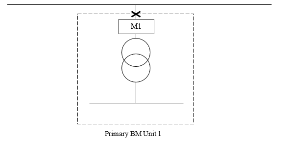
4.1.2 Primary BM Units

Before Aggregation Rules can be submitted for Primary BM Units the Primary BM Units have to be defined and registered in accordance with Section K of the Code and BSCP15.

Detailed below are examples of typical Primary BM Unit configurations for both generators and Suppliers. These are examples and Parties can submit different Primary BM Unit configurations so long as the configuration is in accordance with the Code Rules and associated BSCP.

These examples do not include the application of (Distribution) Line Loss Factors (LLFs) in the interests of clarity. LLFs shall be applied as a multiplying factor to the values for each metering subsystem where appropriate. Where a Party requires the application of separate LLFs for Import and Export metering, the Party may register two separate MSIDs prior to the application of Aggregation rules.

Key

complex image of process

4.1.3 Simplified Power Station
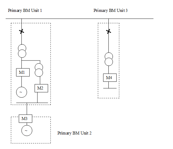
complex image of process

The above is a simplified example of a power station connected to the Transmission System. The power station is owned and operated by Star Power. Star Power has configured the power station into 3 Primary BM Units. Primary BM Unit 1 comprises the main Generating Unit and the associated demand for that Generating Unit. Primary BM Unit 2 is an auxiliary Generating Unit. As the auxiliary Generating Unit has different operating costs to the main Generating Unit the Star Power wants to be able to submit Bids and Offers for each generator independently and therefore has declared the auxiliary Generating Unit as a separate Primary BM Unit. Primary BM Unit 3 is the main station demand. If Star Power did not trade the auxiliary Generating Unit separately, then M1, M2, and M3 could be configured as a single Primary BM Unit.

All the meters in the above example are connected to one Outstation and constitute one Metering System. This Metering System has been registered by Star Power and the Metering System ID is 1234. The 4 physical meters (M1, M2, M3, M4) are 4 metering subsystems, referred to as STAR1, STAR2, STAR3 and STAR4 respectively, contained within the Metering System 1234.

For this example, three sets of Aggregation Rules need to be submitted to calculate the Metered Volumes associated with Primary BM Unit 1, 2 and 3.

Aggregation Rules

Primary BM Unit 1 =

[1234.STAR1.AE – 1234.STAR1.AI] + [1234.STAR2.AE – 1234.STAR2.AI] - [1234.STAR3.AE – 1234.STAR3.AI]

Primary BM Unit 2 =

[1234.STAR3.AE – 1234.STAR3.AI]

Primary BM Unit 3 =

[1234.STAR4.AE – 1234.STAR4.AI]

4.1.4 Power Station with Switchable Auxiliary Generating Unit
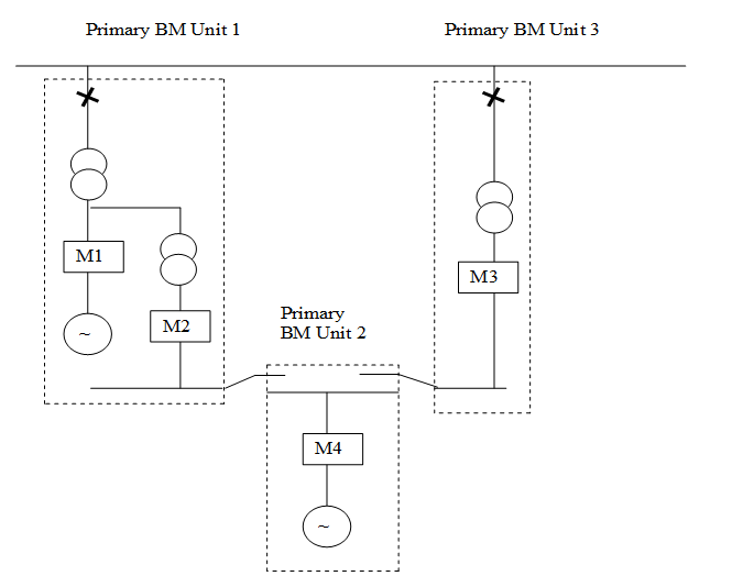
complex image of process

In this example the power station is owned and operated by Star Power. There are three Primary BM Units, Primary BM Unit 1 comprises the main generating unit and the associated demand for that Generating Unit, Primary BM Unit 2 is an auxiliary Generating Unit and Primary BM Unit 3 is the main station demand.

For this example the auxiliary Generating Unit is switchable. It can be connected to the Total System through either Primary BM Unit 1 or Primary BM Unit 3. Typically the auxiliary Generating Unit would be connected through Primary BM Unit 1. However, if the main Generating Unit was shut down, then the auxiliary could be connected through Primary BM Unit 3.

All the meters in the above example are connected to one Outstation and constitute one Metering System. This Metering System has been registered by Star Power and the Metering System ID is 1235. The four physical meters (M1, M2, M3 and M4) are four metering subsystems, referred to as STAR1, STAR2, STAR3 and STAR4 respectively contained within the Metering System 1235.

Aggregation Rules

Parties should register their Aggregation Rules using one of the following assumptions:

Assumption 1 – Primary BM Unit 2 connected through Primary BM Unit 1

Primary BM Unit 1 =

[1235.STAR1.AE – 1235.STAR1.AI] + [1235.STAR2.AE – 1235.STAR2.AI] - [1235.STAR4.AE – 1235.STAR4.AI]

Primary BM Unit 2 =

[1235.STAR4.AE – 1235.STAR4.AI]

Primary BM Unit 3 =

[1235.STAR3.AE – 1235.STAR3.AI]

Assumption 2 – Primary BM Unit 2 connected through Primary BM Unit 3

Primary BM Unit 1 =

[1235.STAR1.AE – 1235.STAR1.AI] + [1235.STAR2.AE – 1235.STAR2.AI]

Primary BM Unit 2 =

[1235.STAR4.AE – 1235.STAR4.AI]

Primary BM Unit 3 =

[1235.STAR3.AE – 1235.STAR3.AI] - [1235.STAR4.AE – 1235.STAR4.AI]

Whichever assumption is used will give the overall correct answer on a Trading Unit basis. The FPNs submitted by Parties can be submitted on the basis of whichever assumption is used.

The actual impact can better be seen by applying some actual meter readings to the above example:

Assuming the auxiliary Generating Unit is in operation and is connected through Primary BM Unit 1, the following metered data would be obtained. Then whichever Aggregation Rule assumption is chosen the end result is the same at the Trading Unit level.

Active Import (MWh)

Active Export (MWh)

Meter 1 (M1)

0

500

Meter 2 (M2)

0

50

Meter 3 (M3)

100

0

Meter 4 (M4)

0

50

Primary BM Unit 1

Primary BM Unit 2

Primary BM Unit 3

Trading Unit

Net Volume

Primary BM Unit volumes calculated through Aggregation Rules 1

(Assumption 1)

(500 - 0) + (50 - 0) - (50 - 0) =

+500

(50 – 0) =

+50

(0 – 100) =

-100

+450

Primary BM Unit volumes calculated through Aggregation Rules 2

(Assumption 2)

(500 – 0) + (50 – 0) =

+550

(50 – 0) =

+50

(0 – 100) – (50 –0) =

-150

+450

4.1.5 Combined Cycle Power Station
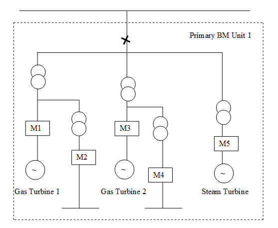
complex image of process

This example comprises of two gas fired turbines and one steam turbine connected to the Transmission System. The equipment is owned and operated by Star Power. The equipment cannot be independently operated and therefore Star Power has registered them as one Primary BM Unit.

All the Meters in the above example are connected to one Outstation and constitute one Metering System. This Metering System has been registered by Star Power and the Metering System ID is 1236. The 5 physical Meters (M1, M2, M3, M4 & M5) are 5 metering subsystems, referred to as STAR1, STAR2, STAR3, STAR4 and STAR5 respectively, contained within the Metering System1236.

Primary BM Unit 1 =

[1236.STAR1.AE – 1236.STAR1.AI] + [1236.STAR2.AE – 1236.STAR2.AI] + [1236.STAR3.AE – 1236.STAR3.AI] + [1236.STAR4.AE – 1236.STAR4.AI] + [1236.STAR5.AE – 1236.STAR5.AI]

4.1.6 Grid Supply Points and GSP Group Takes

GSPs are a number of Systems Connection Points at the same location at which the Transmission System is connected to a Distribution System. The submission of Aggregation Rules for GSPs and GSP Groups are the responsibility of the Distribution System Operator. The submission of Aggregation Rules for GSP Group Take is the responsibility of the CDCA.

Note that the term Grid Supply Point (as used in the BSC and in this BSCP) includes Offshore Transmission Connection Points i.e. points at which the Offshore Transmission System connects to an onshore Distribution System. The process for submitting Aggregation Rules for Offshore Transmission Connection Points is the same as for other Grid Supply Points.

Section 4.1.7 describes two different examples of a shared GSP. Section 4.1.8 describes a typical GSP which includes a Distribution Systems Connection Point and GSP Group Take.

Sections 4.1.9-4.1.11 describe different scenarios with embedded Distribution Systems where there is more than one Distribution System Operator within a single GSP Group.

4.1.7 Shared Grid Supply Point

The following Examples 1A and 1B apply to England and Wales, where the 132kV system is normally a distribution asset.

Example 1A: GSP shared between two GSP Groups:

complex image of process

In this example the GSP is shared between two GSP Groups. The LDSO for GSP Group 1 is Star Power and for GSP Group 2 is Gold Power. Since it is a shared GSP, the 132kV busbar is a transmission asset.

The Codes of Practice state that the defined Metering Point should be at the Systems Connections Points of each LDSO to the common busbar. In this example Star Power have not metered their four circuits, instead they have a valid Metering Dispensation to utilise a difference metering scheme. They submit Aggregation Rules which subtract the energy taken by Gold Power (measured by M3 and M4) from the GSP Group 1 Metered Volume.

In this example Star Power has four feeders as opposed to Gold Power’s two, and has elected to be the majority LDSO. Star Power (as the majority LDSO) would therefore register the metering M1 and M2 and would be responsible for registering the Aggregation Rules for the Metered Volume for the GSP. Both M1 and M2 belong to the same Metering System and the Metering System is allocated the identifier 1234. The physical meters M1 and M2 have metering subsystems identifiers of STAR1 and STAR2 respectively.

Gold Power is the LDSO for GSP Group 2 and would register the metering M3 and M4. Both M3 and M4 belong to the same Metering System and that Metering System is allocated the identifier 5678 and the physical meters M3 and M4 have metering subsystems GOLD1 and GOLD2.

GSP Metered Volume

[1234.STAR1.AE -1234.STAR1.AI] + [1234.STAR2.AE – 1234.STAR2.AI]

GSP Group 1 Metered Volume

[1234.STAR1.AE – 1234.STAR1.AI] + [1234.STAR2.AE – 1234.STAR2.AI] – [5678.GOLD1.AE – 5678.GOLD1.AI] – [5678.GOLD2.AE – 5678.GOLD2.AI] + the Aggregation Rules for all other GSPs within GSP Group 1 + the Aggregation Rules for all DSCPs connecting to/from GSP Group 1

This would be submitted by Star Power.

GSP Group 2 Metered Volume

[5678.GOLD1.AE – 5678.GOLD1.AI] + [5678.GOLD2.AE – 5678.GOLD2.AI] + the Aggregation Rules for all other GSPs within GSP Group 2 + the Aggregation Rules for all DSCPs connecting to/from GSP Group 2
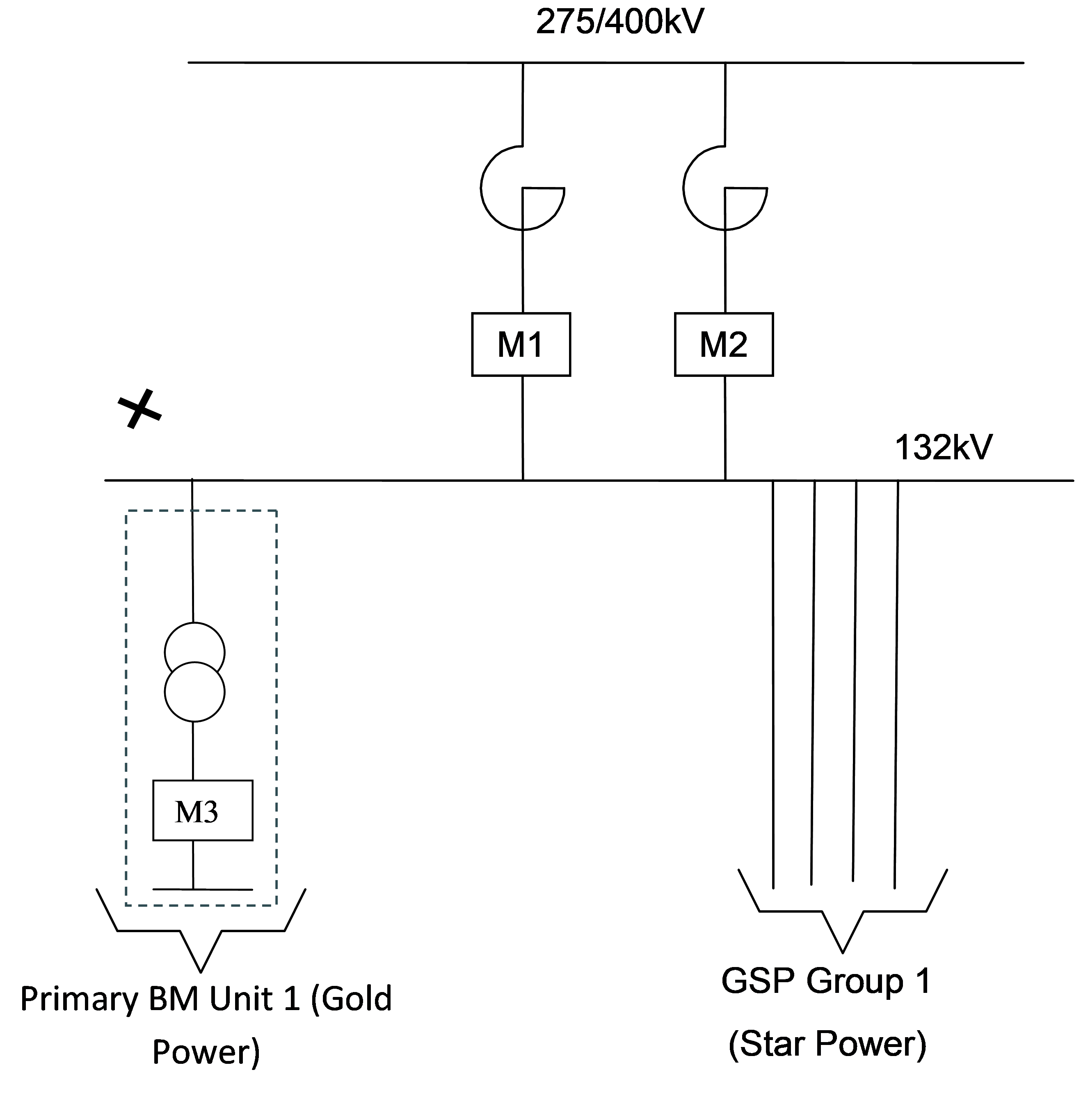
This would be submitted by Gold Power.

Example 1B: GSP shared between a GSP Group and a Primary BM Unit:

complex image of process

In this example the GSP is shared between a GSP Group, for which Star Power is the LDSO, and the Primary BM Unit owned by Gold Power. Since it is a shared GSP, the 132kV busbar is a transmission asset, and the Primary BM Unit is therefore directly connected. The Codes of Practice state that the defined Metering Point should be at the Systems Connections Points to the common busbar. In this example Star Power have not metered their four circuits, instead they have a valid Metering Dispensation to utilise a difference metering scheme. They submit Aggregation Rules which subtract the energy taken by Gold Power (measured by M3) from the total GSP energy flow (as measured by M1 and M2).

Star Power would register the metering M1 and M2 and would be responsible for registering the Aggregation Rules for the Metered Volume for the GSP. Both M1 and M2 belong to the same Metering System and that the Metering System is allocated the identifier 1234. The physical meters M1 and M2 have metering subsystems identifiers of STAR1 and STAR2 respectively.

Gold Power is the Lead Party for Primary BM Unit 1 and would register the metering M3 and would be responsible for registering the Aggregation Rules for Primary BM Unit 1. M3 is allocated the identifier 5678 and the physical meter has metering subsystem GOLD1.

GSP Metered Volume

[1234.STAR1.AE -1234.STAR1.AI] + [1234.STAR2.AE – 1234.STAR2.AI] - [5678.GOLD1.AE – 5678.GOLD1.AI]

GSP Group 1 Metered Volume

[1234.STAR1.AE – 1234.STAR1.AI] + [1234.STAR2.AE – 1234.STAR2.AI] – [5678.GOLD1.AE – 5678.GOLD1.AI] + the Aggregation Rules for all other GSPs within GSP Group 1 + the Aggregation Rules for all DSCPs connecting to/from GSP Group 1

This would be submitted by Star Power.

Primary BM Unit 1 Metered Volume

[5678.GOLD1.AE – 5678.GOLD1.AI]

This would be submitted by Gold Power.

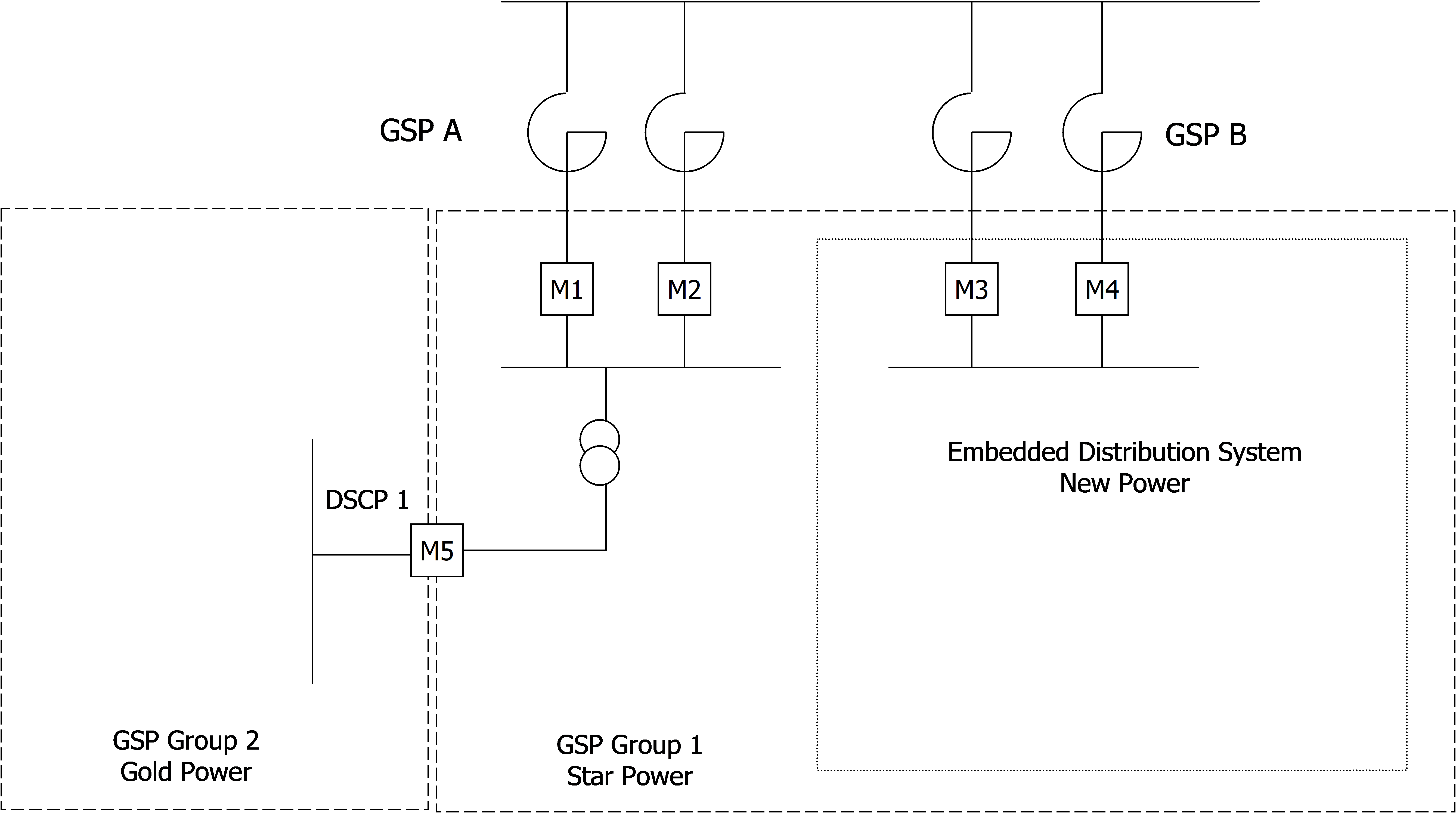
4.1.8 Typical GSP including DSCP and GSP Group Take
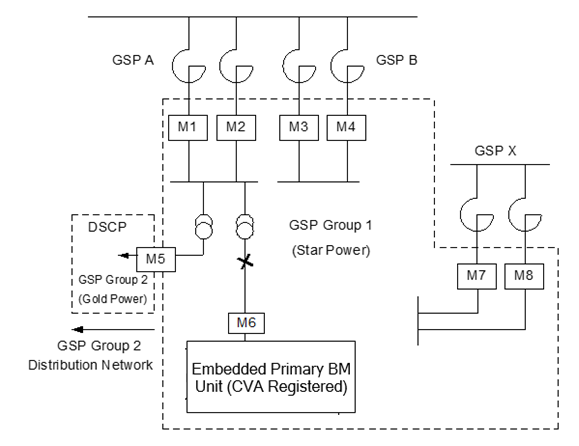
complex image of process

In this example the LDSO for GSP Group 1 is Star Power and for GSP Group 2 is Gold Power.

Star Power have registered the GSP Metering Systems at GSP A, GSP B and GSP X with the Metering System identifiers 1239, 1240 and 1241 respectively. Each of the Metering Systems have metering subsystems associated with them. GSP A has metering subsystems STAR1 and STAR2, GSP B has metering subsystems STAR3 and STAR4 and GSP X has metering subsystems STAR7 and STAR8.

The DSCP is metered by M5. This belongs to the Metering System ID 1231 registered by Gold Power. The physical meter M5 corresponds to a metering subsystem identified as GOLD5. The Metering System ID 1231 has an associated Line Loss Factors Code LLF1.

The embedded Primary BM Unit is a licence exempt generator owned by Green Inc. The Exempt Export Primary BM Unit is registered with the CRA by Green Inc and the Primary BM Unit ID is GREEN_BM. The Metering System associated with the meter M6 is registered by Green Inc and has a Metering System ID 1200 with metering subsystem ID GREEN6 and associated Line Loss Factors Code LLF2.

Aggregation Rules for GSP Metered Volumes

GSP A =

[1239.STAR1.AE – 1239.STAR1.AI] + [1239.STAR2.AE – 1239.STAR2.AI]

This would be submitted by Star Power.

GSP B =

[1240.STAR3.AE – 1240.STAR3.AI] + [1240.STAR4.AE – 1240.STAR4.AI]

This would be submitted by Star Power.

GSP X =

[1241.STAR7.AE – 1241.STAR7.AI]+ [1241.STAR8.AE – 1241.STAR8.AI]

This would be submitted by Star Power.

Aggregation Rules for GSP Group Metered Volumes and GSP Group Take

Metered Volume for GSP Group 1 =

[GSP A] + [GSP B] + [GSP X] – [[1231.GOLD5.AE – 1231.GOLD5.AI] * LLF1] + the Aggregation Rules for all DSCPs connecting to/from GSP Group 1

This would be submitted by Star Power.

Metered Volume for GSP Group 2 =

Aggregation Rules for all GSPs within GSP Group 2 + [[1231.GOLD5.AE – 1231.GOLD5.AI] * LLF1] + the Aggregation Rules for all DSCPs connecting to/from GSP Group 2

This would be submitted by Gold Power.

Green_BM =

[1200.GREEN6.AE – 1200.GREEN6.AI] * LLF2

This would be submitted by Green Inc.

Group Take for GSP Group 1 =

Metered Volume for GSP Group 1 - Green_BM

Group Take for GSP Group 2 =

Metered Volume for GSP Group 2 – all embedded Primary BM Units

These will be established by the CDCA. Parties are not required to submit these Aggregation Rules, however the CDCA can request that they do.

Note:

In this example, the Metering System at the DSCP (M5) is registered by Gold Power. As a result, the above Aggregation Rules treat an Export as the flow from GSP Group 2 to GSP Group 1 and an Import as a flow of electricity from GSP Group 1 to GSP Group 2. However, in practice, the DSCP metering could be registered by either Gold Power or Star Power. If Star Power registered the Metering System at the DSCP then an Export would be from GSP Group 1 to GSP Group 2 and an Import from GSP Group 2 to GSP Group 1.

4.1.9 Distribution System with all its Boundary Points registered in SMRS, entirely embedded within another Distribution System
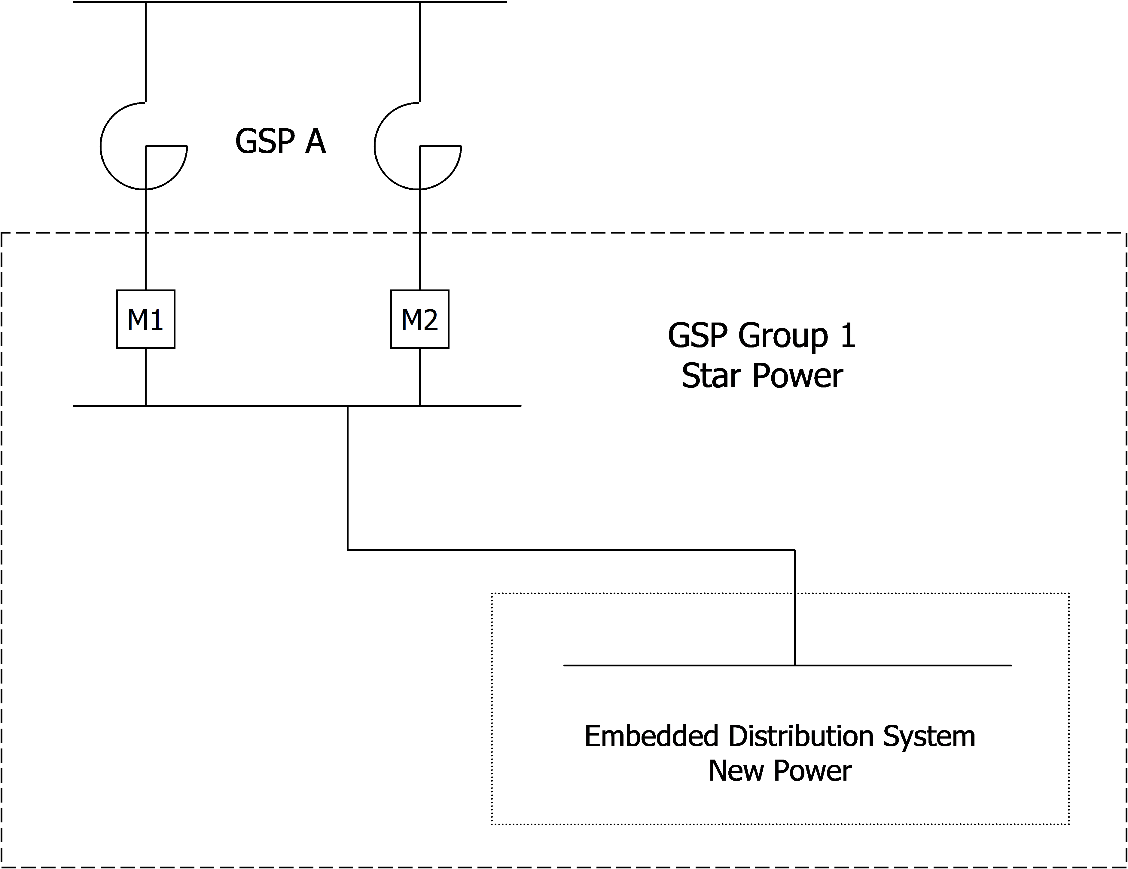
complex image of process

In this example, there are two Distribution Systems and two LDSOs in GSP Group 1. Star Power is the Nominated LDSO (i.e. ex-Public Distribution System Operator) for GSP Group 1 and New Power is an embedded LDSO).

Star Power has registered the GSP Metering Systems at GSP A with the Metering System identifiers 1239. This Metering System has metering subsystems STAR1 and STAR2 associated with it at GSP A.

Aggregation Rules for GSP Metered Volumes

GSP A =

[1239.STAR1.AE – 1239.STAR1.AI] + [1239.STAR2.AE – 1239.STAR2.AI]

This would be submitted by Star Power.

Aggregation Rules for GSP Group Metered Volumes and GSP Group Take

Metered Volume for GSP Group 1 =

[GSP A] + the Aggregation Rules for all other GSPs within GSP Group 1 + the Aggregation Rules for all DSCPs connecting to/from GSP Group 1

This would be submitted by Star Power.

The Group Take for GSP Group 1 is the same as the GSP Group Metered Volume as the embedded Distribution System has no CVA Boundary Points in GSP Group 1 and no contribution to the Aggregation Rules. All the energy of the embedded Distribution System is accounted for in SVA.

Group Take for GSP Group 1 =

Metered Volume for GSP Group 1 - all embedded Primary BM Units

This will be established by the CDCA. Parties are not required to submit these Aggregation Rules, however the CDCA can request that they do.

4.1.10 Distribution System entirely embedded within an existing Distribution System with one embedded Primary BM Unit registered in CVA and all other entry/exit points registered in SVA
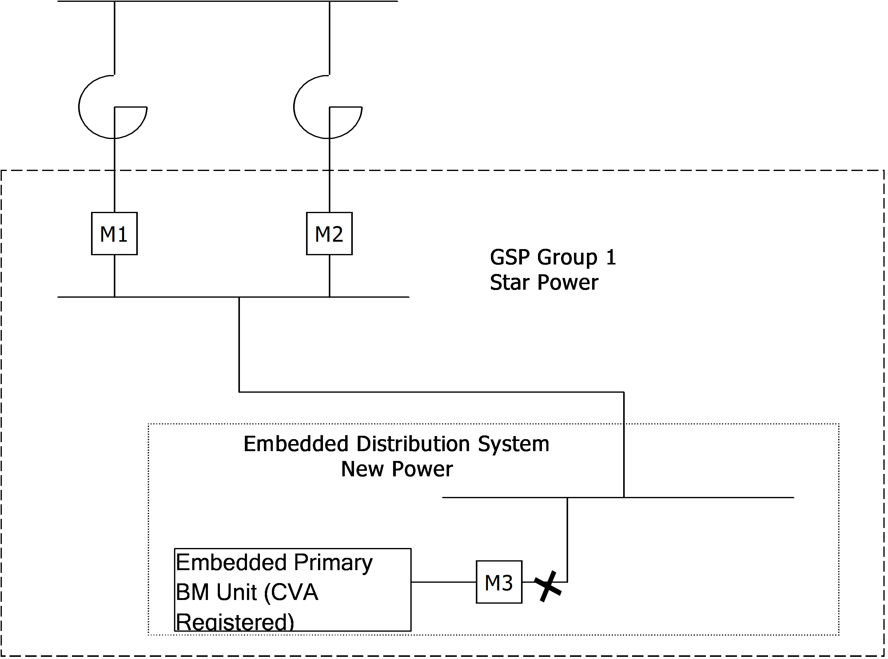
complex image of process

In this example, there are two Distribution Systems and two LDSOs in GSP Group 1. Star Power is the Nominated LDSO for GSP Group 1 and New Power is an embedded LDSO. The embedded Primary BM Unit within New Power's Distribution System is a licence exempt generator owned by Green Inc.

Star Power has registered the GSP Metering Systems at GSP A with the Metering System identifiers 1239. This Metering System has metering subsystems STAR1 and STAR2 associated with it at GSP A.

The Primary BM Unit is registered with the CRA by Green Inc and the Primary BM Unit ID is GREEN_BM. The Metering System associated with the meter M3 is registered by Green Inc and has a Metering System ID 1200 with metering subsystem ID GREEN3 and associated Line Loss Factors Code LLF1.

Aggregation Rules for GSP Metered Volumes

GSP A =

[1239.STAR1.AE – 1239.STAR1.AI] + [1239.STAR2.AE – 1239.STAR2.AI]

This would be submitted by Star Power.

Aggregation Rules for GSP Group Metered Volumes and GSP Group Take

Metered Volume for GSP Group 1 =

[GSP A] + the Aggregation Rules for all other GSPs within GSP Group 1 + the Aggregation Rules for all DSCPs connecting to/from GSP Group 1

This would be submitted by Star Power.

Green_BM =

[1200.GREEN3.AE – 1200.GREEN3.AI] * LLF1

This would be submitted by Green Inc.

Group Take for GSP Group 1 =

Metered Volume for GSP Group 1 - Green_BM - all other embedded Primary BM Units

This will be established by the CDCA. Parties are not required to submit these Aggregation Rules, however the CDCA can request that they do.

4.1.11 Complex Case: Distribution System with two GSP connections to the Transmission System and a DSCP to another Distribution System Operator in a second GSP Group

complex image of process

In this example, there are two Distribution Systems in GSP Group 1. Star Power is the Nominated LDSO for GSP Group 1 and New Power is an embedded LDSO. There is a DSCP to GSP Group 2 where Gold Power is the Nominated LDSO. It should be noted that the Aggregation Rules for GSP Group Metered Volumes would not change if the two GSPs A and B were physically distinct, as they are in the above diagram, or connected.

Star Power has registered the GSP Metering Systems at GSP A with the Metering System identifiers 1239. New Power has registered the GSP Metering Systems at GSP B with the Metering System identifier 1240. Each of the Metering Systems have metering subsystems associated with them. GSP A has metering subsystems STAR1 and STAR2, and GSP B has metering subsystems STAR3 and STAR4.

The DSCP 1 is metered by M5. This belongs to the Metering System ID 1231 registered by Gold Power. The physical meter M5 corresponds to a metering subsystem identified as GOLD5. The Metering System ID 1231 has an associated Line Loss Factors Code LLF1.

Aggregation Rules for GSP Metered Volumes

GSP A =

[1239.STAR1.AE – 1239.STAR1.AI] + [1239.STAR2.AE – 1239.STAR2.AI]

This would be submitted by Star Power.3

GSP B =

[1240.STAR3.AE – 1240.STAR3.AI] + [1240.STAR4.AE – 1240.STAR4.AI]

This would be submitted by New Power.

DSCP 1 =

[[1231.GOLD5.AE – 1231.GOLD5.AI] * LLF1]

This would be submitted by Gold Power.

Note:

In this example, the Metering System at DSCP1 (M5) is registered by Gold Power. As a result, the above Aggregation Rules treat an Export as the flow from GSP Group 2 to GSP Group 1 and an Import as a flow of electricity from GSP Group 1 to GSP Group 2. However, in practice, the DSCP metering could be registered by either Gold Power or Star Power. If Star Power registered the Metering System at the DSCP then an Export would be from GSP Group 1 to GSP Group 2 and an Import from GSP Group 2 to GSP Group 1.

Aggregation Rules for GSP Group Metered Volumes and GSP Group Take

Metered Volume for GSP Group 1 =

[GSP A] + [GSP B] – [DSCP1] + the Aggregation Rules for all other GSPs within GSP Group 1 + the Aggregation Rules for all DSCPs connecting to/from GSP Group 1

This would be submitted by Star Power.

Metered Volume for GSP Group 2 =

Aggregation Rules for all GSPs within GSP Group 2 + [DSCP 1] + the Aggregation Rules for all DSCPs connecting to/from GSP Group 1

This would be submitted by Gold Power.

The Group Take for GSP Group 1 is the same as the GSP Group Metered Volume as the embedded Distribution System has no CVA Boundary Points in GSP Group 1 and no contribution to the Aggregation Rules. All the energy of the embedded Distribution System is accounted for in SVA.

Group Take for GSP Group 1 =

Metered Volume for GSP Group 1

Group Take for GSP Group 2 =

Metered Volume for GSP Group 2 – all embedded Primary BM Units

These will be established by the CDCA. Parties are not required to submit these Aggregation Rules, however the CDCA can request that they do.

4.1.12 Interconnectors
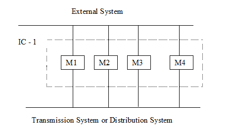
Interconnectors are defined as Apparatus that transfers Electricity to or from the Total System from or to an External System. NGC is responsible for registering the Metering Systems associated with Transmission Interconnectors and submitting the Aggregation Rules. Distribution System Operators are responsible for registering Metering Systems associated with Distribution Interconnectors and submitting the Aggregation Rules.

Below is an example of an Interconnector.

complex image of process

All the Meters in the above example are connected to one Outstation and constitute one Metering System. This Metering System has been registered by NGC and the Metering System ID is 1250. The 4 physical meters (M1, M2, M3 & M4) are 4 steering subsystems, referred to as NGC1, NGC2, NGC3 and NGC4 respectively, contained within the Metering System 1250.

The Aggregation Rule for the above Interconnector will be submitted by NGC.

Metered Volume =

[1250.NGC1.AE – 1250NGC1.AI] + [1250.NGC2.AE – 1250NGC2.AI] + [1250.NGC3.AE – 1250NGC3.AI] + [1250.NGC4.AE – 1250NGC4.AI]
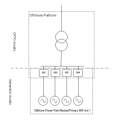
4.1.13 This example below is a simplified example of an offshore wind farm connected to an Offshore Transmission System.

There is a single Offshore Power Park Module owned and operated by STAR Power. The Meters have been installed at the Boundary Points. All of the Meters have integral Outstations which are Registered in CMRS as a single Metering System with MSID 1234. All of the physical Meters (M1, M2, M3 and M4) are 4 metering sub systems, referred to as STAR1, STAR2, STAR3 and STAR4.

For this example 1 set of aggregation rules needs to be submitted to calculate the Metered Volumes associated with Primary BM Unit 1.

Aggregation Rules

Primary BM Unit 1 = [1234.STAR1.AE – 1234.STAR1.AI] + [1234.STAR2.AE – 1234.STAR2.AI] + [1234.STAR3.AE – 1234.STAR3.AI] + [1234.STAR4.AE – 1234.STAR4.AI].

complex image of process

4.1.14 The example below shows a simplified offshore wind farm connected to an Offshore Transmission System. The Registrant has chosen to install a single Meter at location M1 and this is therefore the deemed Boundary Point. As the Meter is not located at the Defined Metering Points the Registrant is required to compensate the Meter readings with values that reflect the power losses between the deemed Boundary Point and the Defined Metering Points.

This may be achieved either within the physical Meter or in the data collection system. For this example the Registrant has applied appropriate compensations within the Meter.

There are two Offshore Power Park Modules owned and operated by STAR Power and these would normally form 2 Primary BM Units. However, in this case, it has been agreed that a single Primary BM Unit is acceptable.

The Meter is Registered in CMRS as a single Metering System with MSID 1234. The physical Meter (M1) is a metering sub system, referred to as STAR1.

For this example 1 set of aggregation rules needs to be submitted to calculate the Metered Volumes associated with Primary BM Unit 1.

Aggregation Rules

Primary BM Unit 1 = [1234.STAR1.AE – 1234.STAR1.AI].

      1. Primary BM Unit 1

complex image of process

4.1.15 Below is a simplified example of an offshore wind farm connected to an Offshore Transmission System. There are two Offshore Power Park Modules owned and operated by RED Power. The two Offshore Platforms are electrically separate but may be coupled for maintenance and other purposes. All of the Meters in this example have integral Outstations which are Registered in CMRS as a single Metering System with MSID 1234. All of the physical Meters (M1, M2, M3, M4, M5, M6, M7 and M8) are 8 metering sub systems, referred to as RED1, RED2, RED3, RED4, RED5, RED6, RED7 and RED8.

For this example 2 sets of aggregation rules need to be submitted to calculate the Metered Volumes associated with Primary BM Unit 1 and 2.

Aggregation Rules

Primary BM Unit 1 = [1234.RED1.AE – 1234.RED1.AI] + [1234.RED2.AE – 1234.RED2.AI] +

[1234.RED3.AE – 1234.RED3.AI] + [1234.RED4.AE – 1234.RED4.AI].

Primary BM Unit 2 = [1234.RED5.AE – 1234.RED5.AI] + [1234.RED6.AE – 1234.RED6.AI] +

[1234.RED7.AE – 1234.RED7.AI] + [1234.RED8.AE – 1234.RED8.AI].

In addition, the Registrant has anticipated that the offshore cable to platform 2 will be disconnected for maintenance purposes. To ensure there is no loss of production during this time the Registrant will re-route the volumes associated with Primary BM Unit 2 through Primary BM Unit 1 by closing the switch marked ‘Normally Open’. The arrangements for this configuration are shown in the following example; however, the Registrant has chosen to pre-submit aggregation rules for this scenario from the outset as follows:

Alternative aggregation rules

Primary BM Unit 1 = [1234.RED1.AE – 1234.RED1.AI] + [1234.RED2.AE – 1234.RED2.AI] +

[1234.RED3.AE – 1234.RED3.AI] + [1234.RED4.AE – 1234.RED4.AI] +

[1234.RED5.AE – 1234.RED5.AI] + [1234.RED6.AE – 1234.RED6.AI] +

[1234.RED7.AE – 1234.RED7.AI] + [1234.RED8.AE – 1234.RED8.AI].

Primary BM Unit 2 = 0.

The alternative aggregation rules will not take effect until the Registrant instructs the CRA to do so by submitting BSCP75/4.4 form.

Other alternative aggregation rules may also be submitted to account for other such anticipated changes to the Primary BM Unit configurations (for example, if the total output is routed via Primary BM Unit 2 because the offshore cable to platform 1 is disconnected).

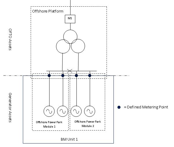
      1. Power Park Module 2/PBMU2

      1. Power Park Module 1/PBMU1

complex image of process

4.1.16 Below are the same arrangements as in the example in section 4.1.15 except the offshore cable to platform 2 has been disconnected for maintenance purposes. The bus section switch has been closed so that the output from Primary BM Unit 2 can be routed via Primary BM Unit 1. In order to reflect the changes to the Primary BM Unit configurations new aggregation rules are required. As the aggregation rules for this new arrangement have already been pre-submitted the Registrant has activated the alternative aggregation rules by submitting BSCP75/4.4 Form.

Aggregation Rules

Primary BM Unit 1 = [1234.RED1.AE – 1234.RED1.AI] + [1234.RED2.AE – 1234.RED2.AI] +

[1234.RED3.AE – 1234.RED3.AI] + [1234.RED4.AE – 1234.RED4.AI] +

[1234.RED5.AE – 1234.RED5.AI] + [1234.RED6.AE – 1234.RED6.AI] +

[1234.RED7. AE – 1234.RED7.AI] + [1234.RED8.AE – 1234.RED8.AI].

Primary BM Unit 2 = 0.

complex image of process

4.1.17 Demand Primary BM Unit

Below is a simplified example of a premises owned and operated by Star Company which is connected directly to the Transmission System. Since the premises has no on-site generation the Registrant wishes to register the premises as a single demand Primary BM Unit (Primary BM Unit 1). A Meter has been installed at the Boundary Point and has an integral Outstation which is registered in CMRS as a single Metering System with MSID 1234. The physical Meter (M1) is the metering subsystem referred to as STAR1.

Since there is no on-site generation, and as this is not a Metering Code of Practice One4 site, the Active Energy Meter is only set up to record Active Import volumes (AI) only.

For this example, Active Export (AE) is therefore zero in the Aggregation Rule. It should be noted that the zero (representing AE) must be accounted for in the Aggregation Rule in order to produce the correct sign (i.e. a negative Metered Volume) for the Metered Volumes for this Primary BM Unit.

Aggregation Rule

Primary BM Unit 1 = [0 – 1234.STAR1.AI]

complex image of process

4.2 BSCP75/4.2 Registration of Meter Aggregation Rules For Volume Allocation Units

Page 1 of 3

To: CDCA

Date Sent: __________

From: Participant Details

Party ID: ______________________________

Name of Sender: _________________________

Participation Capacity: ____________________

Contact email address: _____________________

Our Ref: _______________________________

Contact Tel. No. _________________________

Name of Authorised Signatory: ______________________________________________________

Authorised Signature: ______________________

Password: ___________________

Tick box if this is a Registration Transfer in accordance with BSCP68.

Section 1

Please Tick Aggregation Unit Type

Primary BM Unit

(B)

External Interconnector

(I)

Internal Interconnector

(D)

Grid Supply Point

(P)

Grid Supply Point Group Take

(G)

Aggregation Unit ID

Aggregation Unit Name (optional)

Effective From Date

Effective To Date (optional)

Tick box if submitting multiple sets of Aggregation Rules (each reflecting a different operational configuration) for a Primary BM Unit in a Switching Group.

If you have ticked this box, each set of Aggregation Rules should be submitted on a separate copy of Section 2, each one identified by an appropriate description of the operational configuration (e.g. ‘Normal Running’, ‘Circuit 2 Outage’).

Page 2 of 3

Section 2

Operational Configuration:

(Applies only to Primary BM Units in a Switching Group that require different Aggregation Rules depending on the operational configuration.)

Expression Reference (ER)

MSQ, ER, BMU, GSP, DSCP, LLF or CST

Reference

+, -, /, x

MSQ, ER BMU, GSP, DSCP, LLF or CST

Reference

1

2

3

4

5

6

7

8

9

10

11

12

13

14

15

16

17

18

19

20

21

Page 3 of 3

Section 3

From CDCA to Registrant

I hereby confirm that the Meter Aggregation Rules associated with the above Reference No. have been received.

Input by: Signed:…………………. Name:……………………… Date:…………………………..

Checked by: Signed:…………………. Name:……………………… Date:…………………………..

(For CDCA)

4.3 Examples of Registration Form (Section 2 of Form BSCP75/4.2)

Example 1 Power Station Connected to the Transmission System (based on Primary BM Unit 1 in Section 4.1.3 of this BSCP)

Expression Reference

ER

MSQ, ER, BMU, GSP, DSCP, LLF or CST

Reference

+, -, /, x

MSQ, ER, BMU, GSP, DSCP, LLF or CST

Reference

1

ER

2

-

ER

5

2

ER

3

+

ER

4

3

MSQ

1234.STAR1.AE

-

MSQ

1234.STAR1.AI

4

MSQ

1234.STAR2.AE

-

MSQ

1234.STAR2.AI

5

MSQ

1234.STAR3.AE

-

MSQ

1234.STAR3.AI

6

7

8

Example 2 Power Station Embedded within a Distribution System (based on Primary BM Unit 1 in Section 4.1.3 of this BSCP)

Expression Reference

ER

MSQ, ER, BMU, GSP, DSCP, LLF or CST

Reference

+, -, /, x

MSQ, ER, BMU, GSP, DSCP, LLF or CST

Reference

1

ER

2

-

ER

5

2

ER

3

+

ER

4

3

ER

6

x

LLF

4

ER

7

x

LLF

5

ER

8

x

LLF

6

MSQ

1234.STAR1.AE

-

MSQ

1234.STAR1.AI

7

MSQ

1234.STAR2.AE

-

MSQ

1234.STAR2.AI

8

MSQ

1234.STAR3.AE

-

MSQ

1234.STAR3.AI

9

10

4.4 BSCP75/4.4 Election of Pre-Registered Aggregation Rule for Switching Group

Page 1 of 1

To: CDCA

Date Sent: __________

From: Participant Details

Party ID: ______________________________

Name of Sender: _________________________

Participation Capacity: ____________________

Contact email address: _____________________

Our Ref: _______________________________

Contact Tel. No. _________________________

Name of Authorised Signatory: ______________________________________________________

Authorised Signature: ______________________

Password: ___________________

I hereby elect that the initial Aggregation Rules for the Primary BM Unit shall be:

I hereby elect to switch Aggregation Rules for the following Primary BM Units (in order to reflect a change in operational configuration):

Primary BM Unit ID(s)

New Operational Configuration (as specified on pre-registered Aggregation Rules)

Date and time5 that configuration was switched:

1 This process is applicable to Power Park Module Primary BM Units that are capable of operational switching.

2 Where multiple sets of Aggregation Rules are being registered, also send BSCP75/4.4 to indicate which set is the initial operation set.

3 Changes to GSP Groups must be performed in accordance with BSC Section K1.8, which ensures that all Parties are aware of the changes.

4 Metering Code of Practice One (CoP1) states that both Import MWh and Export MWh are required for Settlement purposes, which means that the metering must be configured to record both Active Import and Active Export (but does not necessarily imply that the Active Export must be allocated to a Primary BM Unit, as Settlement of Export from Exemptable Generating Plant is subject to the provisions of BSC Section K1.2.2(a)(ii)). Code of Practice Two and Code of Practice Three require that Export (or Import) metering need only be installed where required to meet system or plant conditions.

5 Date and time are not required for the initial election, as date comes from the form submission.