Replacement Reserve Schedule Methodology
Effective Date: 7 November 2019
Implementation Date | Version | Description of Change | Mods/ Panel/ Committee Refs |
| 0.1 | Draft for ELEXON review | |
| 0.2 | Draft for industry review | |
| 0.3 | Updated following industry review | |
| 0.4 | Updated following further discussion of review comments with respondents | |
| 1.0 | Approved by BSC Panel | P287/11 |
| 1.1 | Updated to incorporate minor clarifications to change process and treatment of discontinuities in baseline. | |
07/11/2019 | 2.0 | P386 Self-Governance | P289/11 |
Intellectual Property Rights, Copyright and Disclaimer The copyright and other intellectual property rights in this document are vested in ELEXON or appear with the consent of the copyright owner. These materials are made available for you for the purposes of your participation in the electricity industry. If you have an interest in the electricity industry, you may view, download, copy, distribute, modify, transmit, publish, sell or create derivative works (in whatever format) from this document or in other cases use for personal academic or other non-commercial purposes. All copyright and other proprietary notices contained in the document must be retained on any copy you make. All other rights of the copyright owner not expressly dealt with above are reserved. No representation, warranty or guarantee is made that the information in this document is accurate or complete. While care is taken in the collection and provision of this information, ELEXON Limited shall not be liable for any errors, omissions, misstatements or mistakes in any information or damages resulting from the use of this information or action taken in reliance on it. |
This document is the
Replacement Reserve (RR) Schedule Methodology Document. Section T1.14 of the Balancing and
Settlement Code (BSC) requires the BSC
Panel to establish this document (and subsequently have it in force at all times), for the purpose of settling
Replacement Reserve (RR) delivered by Balancing Service Providers (BSPs) in
Great Britain (GB). This BSC requirement arises from the implementation of BSC Modification P344 (‘
Project TERRE implementation into GB market arrangements’).
The BSC requires that this RR Schedule Methodology Document contains detailed requirements for BSC Settlement processes to deem Acceptance Volume Pairs (qAkit) representing the instructions that the National Electricity Transmission System Operator (NETSO) would need to issue to a BM Unit in order to instruct it to deliver the results of each Replacement Reserve Auction.
1.2 What is Project TERRE?
Project TERRE is a project established by European Transmission System Operators (TSOs) to establish an auction platform (‘LIBRA’) through which they can purchase Replacement Reserve from BSPs. The auction will run once per hour (from December 2019) in order to select which offers of RR to activate in order to meet the needs of TSOs, in accordance with the following timetable:
Deadline | Action |
H-60 (BEGCT) | Balancing Energy Gate Closure Time (BEGCT) is the deadline for BSPs to submit RR offers to their national TSO (which in GB is the NETSO). |
H-45 | TSOs submit RR offers (and their needs for RR) to the LIBRA auction platform. |
H-30 | The auction platform informs TSOs of which RR offers should be activated. |
H-25 | The TSO activates the selected BSPs. In GB this activation takes the form of an “RR Instruction” issued by the NETSO to the BM Unit’s Control Point. |
Note that, throughout this document, the term ‘H+N’ refers to the point in time N minutes after the start of the Replacement Reserve Auction Period to which the auction relates. For example, H+30 is the point halfway through the hour; H+65 is the point 5 minutes after the end of the hour; and H-30 is the point thirty minutes before the start of the hour.
1.3 Why does the BSC require an RR Schedule?
The primary purpose of the RR Schedule is to define the volume of energy that a BM Unit must deliver in each Settlement Period, in order to be treated in Settlement as having fully delivered its RR Activations. Where a BM Unit does not deliver this volume of energy, its Lead Party may be liable to Energy Imbalance Charges and Non-Delivery Charges.
The process for settling RR Activations is different in this respect to the process for settling Bid Offer Acceptances (BOAs) in the Balancing Mechanism (BM), where the BOA issued by the NETSO serves as both:
This approach would not work for RR, because the physical dispatch instruction issued to the BM Unit by the NETSO (the “RR Instruction”) may not fully deliver the RR Activation, if the RR Activation is “infeasible” (i.e. cannot physically be delivered). In general:
The NETSO (in constructing the RR Instruction for issue to the BM Unit’s Control Point) will prioritise Dynamic Data and other Grid Code parameters over delivery of the obligations acquired in the Auction; but
Settlement processes (constructing the RR Schedule ex post for Settlement purposes) will prioritise delivery of the obligations acquired in the Auction over compliance with declared Grid Code Parameters.
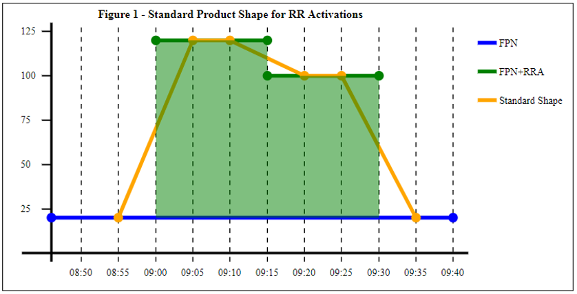
To illustrate these concepts, consider the example of a BM Unit with RR Activations for 100 MW in one Quarter Hour, and 80 MW in the next. These Activations represent an agreement by the BM Unit to increase its output by the relevant amount (above the baseline level defined by the Final Physical Notification). However, the BM Unit does not have to deliver this level of output for the whole fifteen minutes, because the ‘standard product shape’ for RR Activations allows for ten-minute periods to ramp up and down (primarily to avoid large step changes on the system at each Quarter Hour boundary). Figure 1 below illustrates the raw ‘blocks’ of energy allocated in the auction (shaded in green), and the assumed ‘standard product shape’ for delivery of the required volume (in orange):
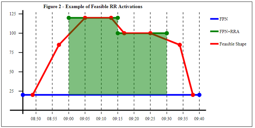
It is recognised that in practice BM Units will not match the standard product shape, due to their varying ramp rates. An RR Activation is defined as “feasible” if the BM Unit’s Dynamic Data and other relevant parameters (e.g. Maximum Export Level) do allow it to deliver the required level of output for the central five minutes of the Quarter Hour. For example, suppose that the BM Unit can deliver the RR Activations shown in Figure 2 as follows. Note that Figure 2 includes the ‘break points’ at which the Run-Up Rate or Run-Down Rate changes, which are required for Settlement purposes (but are not included in instructions sent to Control Points, as per BC2.7.1):
Although the MW profile the BM Unit can deliver (the red line in figure 2) does not exactly match the standard product shape, it does deliver the MW level required by the RR Activation (while also respecting the BM Unit’s declared Run-Up Rates and Run-Down Rates). In this instance we would therefore expect that both the RR Instructions (sent to BSC Systems and the BM Unit’s Control Point by the NETSO) and the RR Schedule (constructed by the BMRA and SAA for Settlement purposes) would match the red profile in Figure 2.
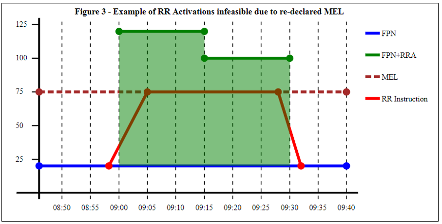
Conversely, an RR Activation is defined as “infeasible” if the BM Unit’s Dynamic Data and other relevant parameters (e.g. Maximum Export Level) do not allow it to deliver the required level of output for the central five minutes of the Quarter Hour. For example, suppose that the RR Activations were as illustrated in Figure 2 above, but that a technical fault required the Lead Party to re-declare the BM Unit’s Maximum Export Limit (MEL) to 75 MW shortly before the results of the Auction became known. In this case the RR Instruction issued by National Grid would not go above MEL, and would therefore not deliver the RR Activation in full, as illustrated in Figure 3:
In this scenario, because the RR Activations are infeasible, the RR Schedule and the RR Instruction will not be the same. The RR Schedule will be unaffected by the re-declaration of MEL, and will therefore match the red profile illustrated in Figure 2 above; while the RR Instruction will match the red profile illustrated in Figure 3.
One of the key functions of the RR Schedule (as described in section 1.3 below) is to calculate whether the BM Unit delivered the required volume of energy. In this scenario, having the Settlement process derive an RR Schedule (rather than relying on the RR Instruction) ensures that the BM Unit is subject to Imbalance Charges and Non-Delivery Charges on that portion of the RR Activation which could not be delivered as a result of the MEL re-declaration.
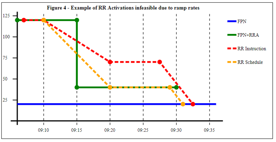
Another scenario that can cause RR Activations to be infeasible is if the change in level between Activations is too large for the BM Unit to complete the necessary ramp within 10 minutes. For example, consider a scenario identical to that illustrated in Figure 2, except that the auction platform only accepts 20 MW in the second Quarter Hour. If this means that the change in level between the two Quarter Hours is too great for the BM Unit to complete, the RR Instruction and RR Schedule will be constructed differently, as illustrated in Figure 4. The RR Instruction (in red) ramps down for ten minutes, following the declared Run-Down Rates, and as a result cannot reach the level of the RR Activation. The RR Schedule (in orange) ramps down for ten minutes to reach the required level (even though this requires a faster Run-Down that declared under the Grid Code), in accordance with Principle 8 in section 2.2:
1.4 What is the RR Schedule used for in Settlement?
This section 1.4 summarises the various ways in which the Settlement Administration Agent (SAA) uses RR Schedules in Settlement calculations:
Setting the baseline from which the volume of subsequent BOAs is measured (see section 1.4.1 below);
Calculation of Balancing Energy Deviation Volumes (see section 1.4.2 below);
Determination of Non-Delivery Volumes and Non-Delivery Charges (see section 1.4.3 below);
Determination of Imbalance Prices (see section 1.4.4 below); and
Adjustment of Energy Imbalance Volumes (see section 1.4.5 below)
The RR Schedules calculated by the SAA will be reported to market participants in the SAA-I014 Settlement Report, in order to provide transparency to the market of how RR is settled.
Items 1 and 4 in the above list are also performed by the Balancing Mechanism Reporting Agent (BMRA), on an indicative basis, for purposes of market reporting.
The information in this section is given as general guidance (to assist parties in understanding the nature and purpose of the RR Schedule Methodology). For the avoidance of doubt, the provisions of the BSC and the other sections of this Methodology take precedence over Section 1 of the Methodology (in the event of any inconsistency between the two).
1.4.1 Setting the baseline for settlement of subsequent BOAs
Section T of the BSC requires that:
For each RR Activation, the Settlement system will construct an RR Schedule; and
For purposes of calculating Acceptance Volumes (qAkij(t)), this RR Schedule will be treated as if it was an Acceptance that had been issued to the BM Unit at the Gate Closure time of the Replacement Reserve Auction Period. The BSC legal text allows this Gate Closure time to be anywhere between 55 and 60 minutes before the start of each hour.
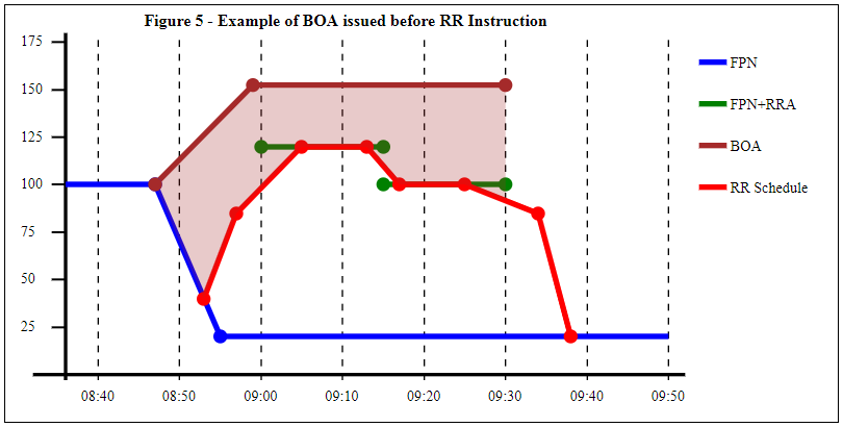
Because the RR Schedule is treated as an Acceptance, it may be used in calculating the acceptance volume of a subsequent BOA. For example, consider the case in which a BOA is issued that is in the same direction as (but larger than) the RR Activation, as shown in Figure 5 below:
Assuming the BOA in Figure 5 is issued after Gate Closure for the Auction Period but before the NETSO could issue an RR Instruction, the volume of the BOA will be calculated from the baseline of the RR Schedule i.e. the volume shaded light brown (and in this instance no RR Instruction would be required). The volume shaded light brown will be subject to BM settlement, and the volume under the RR Schedule would not be treated as part of the BOA volume (because it is delivering the RR Activations, and paid for through the RR Cashflow under RR Settlement rules).
If the BOA in Figure 5 had been issued after the RR Instruction, it would have been the RR Instruction (rather than the RR Schedule) that was used to determine the BOA volume. For a feasible RR Activation this would give the same result (because the RR Schedule and RR Instruction would match).
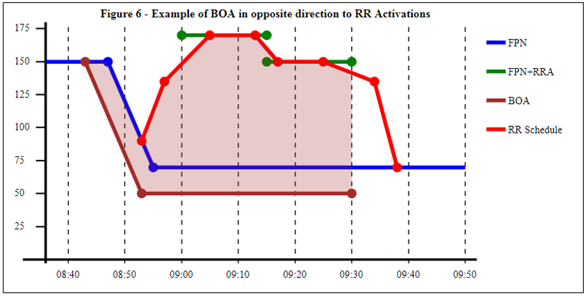
Where a BOA is issued in the opposite direction to the RR Activation (and before the time for issuing RR Instructions), National Grid has indicated that they will not issue an RR Instruction. It will therefore be the RR Schedule that is used to calculate the BOA volume. For example, in Figure 6 below, the BOA is a Bid Acceptance (in the opposite direction to the positive RR Activation). The volume between the RR Schedule and the BOA (shaded brown in the diagram) is therefore treated as a Bid volume:
Note that the NETSO would usually issue another BOA to bring the BM Unit back to FPN (rather than leaving it ‘hanging’ at 09:30. But this BOA could not be issued until after 08:30 (Gate Closure for the Settlement Period starting at 09:30), and is not shown in Figure 6.
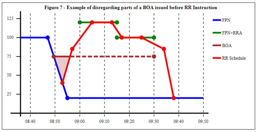
In summary, the general rule illustrated by the above examples is that, for a BOA issued after Gate Closure for the auction period but before the RR Instruction, the difference between the RR Schedule and the BOA will be used to calculate the BOA volume. However, the BSC does recognise one special case as an exception to this general rule. Where the BOA is in the same direction as the RR Activation, but smaller in magnitude than the RR Schedule, Section T3.4.2A states that this part of the BOA should not be treated as an Acceptance for Settlement purposes.
An example of this is illustrated in Figure 7 overleaf. A BOA was issued after Gate Closure for the auction period (but before the RR Instruction), keeping the BM Unit at 75 MW up until 09:30. The part of this BOA shown as dotted in the diagram triggers the above rule, and is effectively ignored for Settlement purposes. This means that the BOA volume (shaded brown in the diagram) does not include any of the area underneath the red line of the RR Schedule:
1.4.2 Calculation of Balancing Energy Deviation Volumes
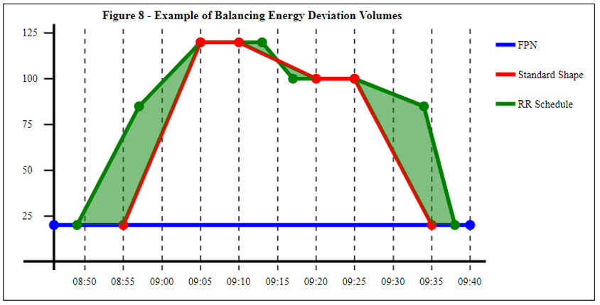
For RR Activations that are feasible, the RR Schedule will generally respect the BM Unit’s declared Run-Up Rates and Run-Down Rates. In many cases this means that the time taken to ramp up or down will not match the standard ten-minutes. For example, in section 1.3 above, the Standard Product Shape (illustrated in Figure 1) was not the same as the RR Schedule (illustrated in Figure 2). The difference in volume between the two shapes is a Balancing Energy Deviation Volume, as illustrated in Figure 8 below:
The green-shaded volumes in Figure 8 represents the difference between the volume of energy that the BM Unit would deliver if following RR Schedule, and the volume it would deliver if following the standard product shape. Section T3.22 of the BSC defines this difference as:
“Replacement Reserve Instructed Offer Deviation” (IODij), where the BM Unit is delivering a positive volume of energy (relative to the baseline), as is the case in Figure 8; or
“Replacement Reserve Instructed Bid Deviation” (IBDij), where the BM Unit is delivering a negative volume of energy (relative to the baseline).
In Figure 8, the small green areas between 09:10 and 09:20 cancel each other out (one being positive, and one negative), which will generally be the case for a BM Unit completing the ramp in ten minutes or less. But the longer ramps at the beginning and end of delivery do create a net deviation volume. In this case the deviation volume represents an additional volume of energy that the BM Unit must deliver, as a result of requiring longer than ten minutes to complete the ramp. The Lead Party will not receive (or be required to make) any payments for these volumes. For example, in the scenario illustrated by Figure 8:
The RR Cashflow paid to the Lead Party is based on the TERRE Clearing Price and the volume of the RR Activation (which equals the volume of the Standard Product Shape). The Lead Party does not receive the TERRE Clearing Price for the additional energy represented by the Instructed Offer Deviation (IODij);
Section T of the BSC does include provision for the Lead Party to receive a Balancing Energy Deviation Price (BEDPj) for the additional deviation volumes; but this price is specified to be zero. A BSC Modification Proposal would be required to allow Lead Parties to receive a non-zero payment for these volumes; and
Although the Lead Party does not receive payment for this additional energy, they must still deliver it, in order to avoid incurring Energy Imbalance Charges and possible Non-Delivery Charges.
Where parties are delivering negative (downward) RR Activations the situation will be reversed:
The RR Cashflow paid by the Lead Party is based on the TERRE Clearing Price and the volume of the RR Activation (which equals the volume of the Standard Product Shape). The Lead Party is not required to pay the TERRE Clearing Price for the additional energy represented by the Instructed Bid Deviation (IBDij);
Section T of the BSC does include provision for the Lead Party to pay a Balancing Energy Deviation Price (BEDPj) for the additional deviation volumes; but this price is specified to be zero. A BSC Modification Proposal would be needed to require Lead Parties to make a non-zero payment for these volumes; and
Although the Lead Party does not make any payment for this additional energy, they must still deliver it, in order to avoid incurring Energy Imbalance Charges.
1.4.3 Determination of Non-Delivery Volumes and Non-Delivery Charges
As explained in section 1.3 above, one of the key reasons for calculating an RR Schedule is to define the volume of energy that a BM Unit must deliver in order to be treated as having fully delivered its RR Activation (and hence not subject to Non-Delivery Charges on the associated payment).
Taking Figure 8 above as an example, the area between the RR Schedule (green line) and the FPN (blue line) is the Period RR Total Accepted Offer Volume (RRAOnij). Most of this volume falls into the half hour from 09:00 – 09:30, but some also into the period before and after. If the BM Unit does not deliver these volumes it will give rise to a Non Delivery Volume, which will be potentially subject to Non Delivery Charges. The calculation of these charges recognises that the Lead Party did not receive payment for all of these RRAOnij volumes:
The volume under the red line in Figure 8 (i.e. the Standard Product Shape) is treated in the calculation as having been paid at the TERRE Clearing Price; and
The additional Balancing Energy Deviation Volume (shaded green in Figure 8) is treated in the calculation as having been paid at a zero price.
1.4.4 Determination of Imbalance Prices
Unlike BOAs, RR Activations are not individually included in the Imbalance Price calculation (because not all of them will be meeting a balancing need in GB). However, the Period RR Total Accepted Offer Volumes (RRAOnij) and Bid Volumes (RRABnij) are used to calculate aggregate balancing actions for inclusion in the pricing stack:
One aggregate action (priced at the TERRE Clearing Price) for the total volume of RR activations scheduled by the auction to meet GB balancing needs; and
Another aggregate action (treated as unpriced) for any remaining RR volume (including the net total of Balancing Energy Deviation Volumes).
1.4.5 Adjustment of Energy Imbalance Volumes
The RRAOnij and RRABnij volumes are also used to adjust the Energy Imbalance Volumes of the relevant party (or parties, in the case of Secondary BM Units), in order to ensure that parties are not subject to Energy Imbalance Charges as a result of successfully delivering instructed RR volumes.
2 PRINCIPLES UNDERLYING THE RR SCHEDULE METHODOLOGY
This section 2 summarises some of the principles underlying the RR Schedule Methodology described in section 3. This information is given as general guidance (to assist parties in understanding the nature and purpose of the RR Schedule Methodology). In the event of any inconsistency between the two sections, section 3 will take precedence (until such time as the inconsistency can be resolved using the change process described in section 4 below).
The
RR Schedule Principles described in this section have been derived from the RR Dispatch principles published by the NETSO in the
GC0097 Final Modification Report; but they are not the same (primarily because non-feasible RR Activations are handled differently in dispatch and settlement, for the reasons described in section
1.3 above). This is discussed in more detail below under Principle 2.
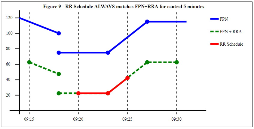
Principle 1 – for the central five minutes of any Quarter Hour where the BM Unit has a non-zero RR Activation, the RR Schedule will always equal the level required to fully deliver the RR Activation:
RR Schedule = FPN + RR Activation
For example, if the BM Unit has an RR Activation of -52.5 MW in the Quarter Hour starting at 09:15, the RR Schedule will definitely be 52.5 MW below the level defined by the FPN, for the five minutes starting at 09:20. This is illustrated in Figure 9 below, with the dotted green line showing the value of FPN + RR Activation. The central five minutes of this (shown in red) will be included in the RR Schedule; while outside this central five minutes the RR Schedule will depend on other factors (such as the declared Run-Up Rates and Run-Down Rates, as discussed in section 2.2 below):
Principle 1 relates to the fundamental purpose of the RR Schedule (as described in section 1.3), which is to define a MW level that the BM Unit must meet in order to be treated (for Settlement purposes) as having fully delivered the RR Activation.
Principle 2 – with certain exceptions (such as infeasible RR Activations), the RR Schedule (calculated for Settlement purposes) should match the RR Instruction (issued to the Control Point by the NETSO).
The purpose of this principle is to ensure that Lead Parties who do follow the RR Instructions issued by the NETSO are protected (as far as possible and appropriate) from Non-Delivery Charges and Energy Imbalance Charges. Nonetheless, there are circumstances in which Principle 2 cannot be followed, and the RR Schedule constructed by Settlement will not match the RR Instruction:
Where the RR Activation cannot be fully delivered due to Dynamic Data or other Grid Code parameters declared by the Lead Party (an “infeasible” RR Activation), the RR Schedule will prioritise Principle 1 over compliance with Grid Code parameters (and will therefore not match the RR Instruction). Section 1.3 above provides examples of this;
In some circumstances, a change in conditions on the system (after data was submitted to the Auction platform) may mean that the NETSO does not issue an RR Instruction (or issues an RR Instruction that is not fully consistent with the RR Activation). The RR Schedule will still reflect the instruction that the NETSO would have issued to deliver the RR Activation, had they been able to do so;
As discussed in Principle 3 below, the NETSO will construct an initial ramp whose starting point is defined by the BM Unit’s “Committed Level” (CL) at the time the RR Instruction is issued. This Committed Level will include BOAs and RR Instructions issued up until this point (approximately H–25), whereas the RR Baseline used to construct the RR Schedule will not include BOAs or RR Instructions issued after the BEGCT (expected to be H–60 or H–55); and
For consistency with current BM processes and data flows, the RR Instruction will round the instruction points to the nearest MW. For consistency with the RR Auction process, the RR schedule will allow power levels to be defined to a tenth of a MW (0.1 MW).
Principle 3 – the RR Schedule will start at (and return to) the “RR Baseline”, which is defined, for times up until the end of RR Auction Period (i.e. H+60), as follows:
RR Baseline = Final Physical Notification (FPN), as modified by any BOAs or RR Instructions issued prior to Gate Closure for the Auction Period to which the RR Activation relates.
Principle 6 below discusses the definition of RR Baseline for times after H+60. Section 3.3.1 below includes an example of how the RR Baseline is constructed.
Because the RR Baseline excludes BOAs and RR Instructions issued after BEGCT, it will not necessarily match the Committed Level used by the NETSO to construct the RR Instruction. Figure 5 (in section 1.4.1 above) provides an example of this:
By the time the NETSO receives the results of the auction, the Committed Level for the BM Unit already includes a BOA that is in the same direction as (and delivers the full volume of) the RR Activation. The NETSO would therefore not issue an RR Instruction; but
For Settlement purposes, the RR Schedule would be constructed using an RR Baseline that does not include the BOA, in order to define how much of the delivered volume should be paid for as Replacement Reserve, and how much paid for as an Offer Acceptance.
2.2 Principles relating to ramps
At each Quarter Hour boundary where the level of a BM Unit’s RR Activation increases or decreases, the RR Schedule Methodology must define the MW profile of the ‘ramps’ that the BM Unit will be expected to follow while running up or running down. The principles adopted can be summarised as follows.
Principle 4: Where Run-Up and Run-Down Rates permit, the Methodology will always schedule ramps that are:
Ten minutes in duration or less;
Have start and end times approximately symmetric around the time of the Quarter Hour boundary; and
Comply with the BM Unit’s declared Run-Up Rates or Run-Down Rates (and associated Elbow Points).
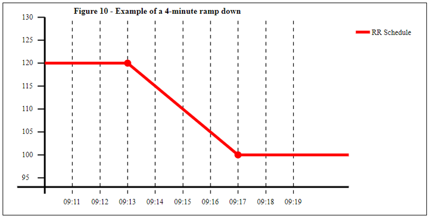
For example, Figure 2 (in section 1.3 above) showed an RR Activation of 100 MW (above the FPN of 20 MW) ending at 09:15, and one of 80 MW beginning. Suppose that the BM Unit’s declared Run-Down Rate is 5 MW/min (with no Elbow Points between 80 MW and 100 MW). It will therefore take 4 minutes to reduce the output from 100 MW to 80 MW. In accordance with Principle 4, the Methodology will schedule the run down to begin at 09:13, and end at 09:17, as shown in Figure 10 below:
However, Principle 4 cannot be applied if the change in the level of the RR Activation is sufficiently large in magnitude that the time taken to run up or down (as determined from the declared Run-Up or Run-Down Rates) exceeds ten minutes. In this case other principles must apply (i.e. Principles 5 to 8 described below).
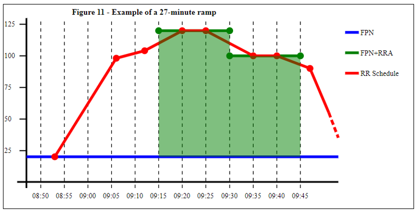
Principle 5: For the first non-zero RR Activation in the hour, the Methodology will schedule ramps that:
Are up to 30 minutes in duration;
Finish five minutes after the start of the Quarter Hour; and
Comply with the BM Unit’s declared Run-Up or Run-Down Rates (provided they do allow the ramp to complete in 30 minutes or less).
“For the first PRRL for which a non-zero RRA was provided up to 30 minutes of ramping time is allowed. The ramp must project back in time to meet the CL of the RR provider. Initially ramps are checked for symmetry as described earlier. If the ramp is a “slow ramp” it will start at +5 minutes into the PRRL and will be projected back to meet the CL for up to a maximum of 30 minutes. If this cannot be achieved the infeasibility rule described below will be applied.”
For example, Figure 11 below shows an example in which the ramp takes 27 minutes to complete. It therefore starts 22 minutes before the Quarter Hour boundary:
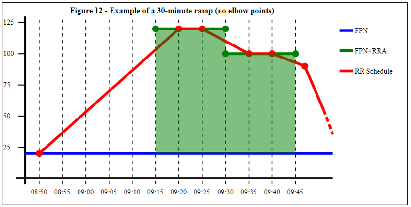
If the declared Run-Up and Run-Down Rates require longer than 30 minutes, the Methodology will not use them, and simply calculate a straight 30-minute run-up or run-down (without elbow points), as illustrated in Figure 12 below:
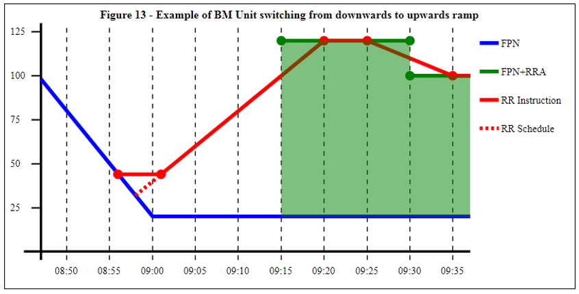
Where the BM Unit is already ramping (according to the RR Baseline) at the point the ramp starts, the RR Schedule Methodology may create RR Schedules in which the BM Unit changes direction instantaneously (a ‘V-shape’). We understand that the NETSO’s dispatching system may seek to avoid this by introducing a level period of five minutes, but Settlement systems will not attempt to duplicate this. Figure 13 overleaf illustrates the type of difference that may arise in this circumstance between the RR Instruction (solid red line) and RR Schedule (dotted red line):
Principle 6: For the last non-zero RR Activation in the hour the Methodology will schedule ramps that:
Start five minutes before the end of the Quarter Hour boundary;
Comply with the BM Unit’s declared Run-Up or Run-Down Rates; and
Have no specific limit on their duration.
“For the last PRRL for which a non-zero RRA was provided there is no limit on ramping time. The ramp must project forwards in time to meet the CL of the RR provider. Initially ramps are checked for symmetry as described earlier. If the ramp is a “slow ramp” it will start at -5 minutes from the end of the PRRL and will be projected forward to meet the CL.”
The Workgroups that developed the P344 and GC0097 solutions recognised that the choice of ‘Committed Level’ for this final ramp to project forward to is potentially problematic, as it relates to Settlement Periods after the end of the RR Auction Period, which will not have passed Gate Closure at the point the auction results become known. This means that:
When the NETSO constructs the RR Instruction (shortly after H-30), it may not have access to FPN data for the period of the final ramp; and
When such FPN data does subsequently become available, it may have been constructed by the Lead Party after they learnt the results of the auction (increasing the risk of Lead Parties manipulating the shape of the final ramp in a manner that provides them with a competitive advantage over other participants in the auction).
To address these issues, we understand the NETSO will if necessary issue two RR Instructions: one shortly after H-30 that covers the bulk of the Auction Period; and one shortly after H (when FPN data becomes available for the Settlement Period following the Auction Period) that covers the remainder of the Auction Period and the entirety of the final ramp. If the final ramp extends beyond H+90 FPN data will not be available, so the final ramp will be projecting forward to meet a CL based on Physical Notifications that are still subject to change by the Lead Party; but any such subsequent changes will not affect the RR Instruction that is issued.
The RR Schedule Methodology adopts a similar approach of constructing the final ramp using only data that is fixed at the point the auction results become known. However, Settlement systems do not have access to the Physical Notifications that were available to the NETSO at H-25 (only to the FPNs that subsequently replaced them). To address this issue, the RR Schedule Methodology will use the RR Instruction issued by the NETSO (where available) to deduce the Committed Level that the NETSO must have used to build the final ramp. This is captured in Principle 7 below:
Principle 7: the “RR Baseline” is defined, for times after the end of RR Auction Period (i.e. H+60), as a flat MW profile whose level is defined by:
The final MW level in the last RR Instruction issued by the NETSO relating to the hour; or
If no such RR Instruction was received, the final value of the FPN in the Settlement Period ending at H+60.
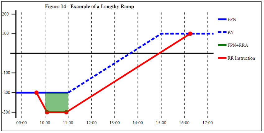
Although it is unlikely to happen in practice, this approach to long ramps (ultimately derived from Rule 5 in the GC0097 Final Modification Report) can in principle give rise to a final ramp lasting many hours, as illustrated in Figure 14 below. In this example the NETSO has constructed an RR Instruction that ramps up to meet the Physical Notification at 16:15 at a level of +100 MW. The Methodology uses this 100 MW level to define the RR Baseline from 11:00 onwards (and will construct a final ramp back up to that level):
Principle 8: In all other cases (where Principles 5 to 7 do not apply) the RR Schedule will assume a straight ramp (with ten minutes duration) from one Quarter Hour to the next.
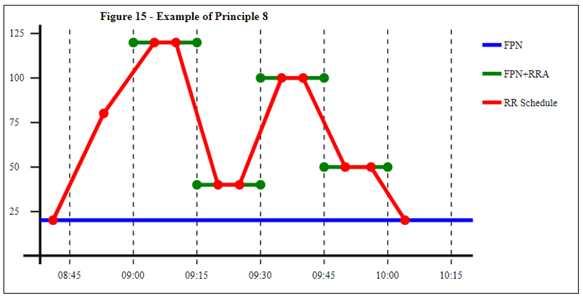
For example, Figure 15 below illustrates a scenario in which:
Principle 5 applies to the start of the first RR Activation (at 9:00), with a ramp up lasting in excess of ten minutes, and respecting declared Run-Up Rates (and associated elbow points);
Principle 4 applies to the end of the last RR Activation (at 10:00), with the step down to FPN sufficiently small that it can be achieved in less than 10 minutes while respecting declared Run-Down Rates; and
Principle 8 applies at the other transitions (9:15, 9:30 and 9:45).
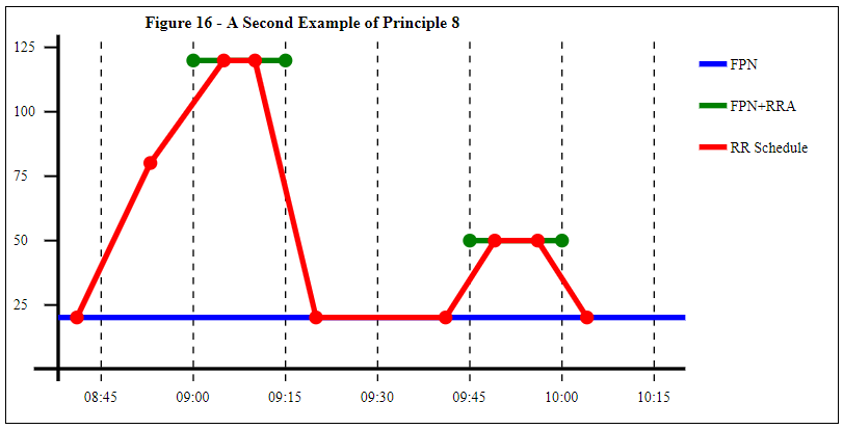
Figure 16 illustrates a similar scenario, but with zero (or no) RR Activations between 09:15 and 09:30. Principle 8 would still apply to the transition at 09:15 (which is too long to complete in 10 minutes):
3 RR Schedule Methodology
This section 3 specifies the RR Schedule Methodology that the BMRA and SAA will use to construct RR Schedules, as required by Sections T and V of the BSC. The Methodology presented here is intended to be consistent with the background information in section 1 and the Principles in section 2; but in the event of any inconsistency this section 3 will take precedence (until such time as the inconsistency can be resolved using the change process described in section 4 below).
The key input data required to calculate the RR Schedule in relation to an hour ‘H’ and BM Unit ‘i' are as follows:
Input Data | Reason Required |
RR Activations for the Auction Period (H to H+60). | RR Activations for the Auction Period define the requirements that the RR Schedule must deliver. |
Run-Up Rates and Run-Down Rates in effect at Gate Closure for the Auction Period | Used to construct ramps, in accordance with the Principles explained in section 2.2 above. |
The Final Physical Notifications for H-30 to H+60 (i.e. the Auction Period, and the half hour before). | Required to define the RR Baseline. |
Any BOAs or RR Instructions covering the period H-30 to H that were issued before Gate Closure for the Auction Period. | Required to define the RR Baseline for the half hour prior to the Auction Period. |
RR Instruction issued by the NETSO in relation to the Auction Period. | Used (if available) to define the baseline for H+60 onwards, in accordance with Principle 7 (explained in section 2.2 above). |
The output of the process is the RR Schedule for the RR Activations within the hour. The RR Schedule is a piecewise linear MW profile, made up of a number of straight line segments each defined by:
From Time and To Time (UTC times on a minute boundary)
From Level and To Level (MW values, to one decimal place)
The RR Schedule for a given hour will start no earlier than H-25, but may continue for hours or days after the end of the Auction Period.
3.2 Process for testing a candidate ramp duration
A number of the Methodology’s process steps require a test of whether it is feasible for the BM Unit to ramp between two given MW profiles, starting at a time t0, and ending at a subsequent time t1. For example:
Is there a ramp (consistent with declared Run-Up Rates) that takes the BM Unit from the RR Baseline to a level 140 MW above the FPN, starting at 14:15 and ending by 14:35?
What ramp (consistent with declared Run-Down Rates) takes the BM Unit from 100 MW above the FPN back to the RR Baseline, starting at 14:40 and with no specific limit on the end time (i.e. the special case where t1 is set arbitrarily far into the future)?
This section explains the method to be used for testing candidate ramp durations in this way (using examples). A more formal statement of the same material is provided in Appendix 2.
To illustrate example 1 above, suppose that the RR Baseline is as specified in the following table:
Example RR Baseline |
Time From | Time To | Level From | Level To |
14:08 | 14:18 | 300 | 175 |
14:18 | 14:25 | 175 | 175 |
14:25 | 14:33 | 175 | 275 |
14:33 | 15:00 | 275 | 275 |
In this example, the Methodology requires us to test whether a ramp starting at 14:15 can reach the required level of 415 MW (140 MW above the RR baseline) by 14:35. The required level is higher than the starting point, so the calculation must use Run-Up Rates, which for the purposes of this example we will assume to be as follows:
Example Run-Up Rates |
RUR1 | Elbow 2 | RUR2 | Elbow 3 | RUR3 |
12.5 MW/min | 330 MW | 3 MW/min | 345 MW | 11 MW/min |
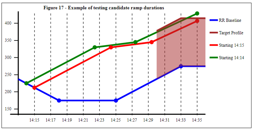
The required calculation is as follows, with the candidate ramp illustrated in red in Figure 17 below:
The ramp starts at 14:15, when the RR Baseline is 212.5 MW
Ramping up at 12.5 MW/min, the ramp will reach elbow 2 (330 MW) at 14:24:24
Ramping up at 3 MW/min, the ramp will reach the next elbow (345 MW) at 14:29:24
Ramping up at 11 MW/min, the ramp will reach 406.6 MW at the end time of 14:35
The candidate ramp starting at 14:15 does not reach the required level (415 MW) at 14:35, which means a ramp starting at 14:15 does not meet the requirement. In this case the Methodology would next test a ramp starting at 14:14 (illustrated in green in Figure 17), as follows:
The ramp starts at 14:14, when the RR Baseline is 225 MW
Ramping up at 12.5 MW/min, the ramp will reach elbow 2 (330 MW) at 14:22:24
Ramping up at 3 MW/min, the ramp will reach the next elbow (345 MW) at 14:27:24
Ramping up at 11 MW/min, the ramp will reach 428.6 MW at the end time of 14:35, having intersected the target profile at approximately 14:33:40
Now the required target level has been met, so this candidate would be accepted. The times for the RR Schedule are as follows. Note that the final point in the profile is the target point at which we were aiming (415 MW at 14:35):
Initial Ramp to be Included in RR Schedule |
Time From | Time To | Level From | Level To |
14:14 | 14:22 | 225 | 330 |
14:22 | 14:27 | 330 | 345 |
14:27 | 14:35 | 345 | 415 |
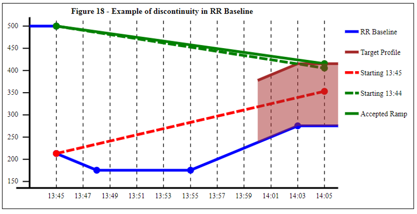
3.2.1 Treatment of Discontinuities in the RR Baseline
The Methodology must also allow for discontinuities (‘jumps’) in the RR Baseline. For example, suppose that in the above example the NETSO had issued a BOA instructing the BM Unit to run at 500 MW until 13:45 (and had done so prior to Gate Closure for the Auction Period, causing it to be included in the RR Baseline). The RR Baseline would in this instance include a discontinuity at 13:45:
In general, the Methodology must be able to test the feasibility of a ramp from time t1 to time t2, where the relevant MW profile has a discontinuity at time t1 and/or time t2. This situation is handled as follows:
For a time t within the Auction Period, the value of the profile at time t is taken as being the limit as one approaches t from the direction of the centre of the Quarter Hour block to which the candidate ramp relates; and
For a time t outside the Auction Period, the Methodology will try both options, starting with the limit as one approaches time t from the direction of the Auction Period.
In the example shown in Figure 18, the Methodology is constructing the ramp up to the first Quarter Hour of the Auction Period. It has already tried candidate ramps with durations from 1 to 19 minutes, and is now required to try the candidate ramp with duration 20 minutes (from 13:45 to 14:05). There is a discontinuity at the start time of 13:45, and because this time falls outside the Auction Period the Methodology would try out two options as follows:
First it would test the possibility of ramping up from 212.5 MW (at 13:45) to 415 MW (at 14:05). This option is tested first because 212.5 MW is the limiting value of the RR Baseline at 13:45 as one approaches from later times (i.e. from the direction of the Auction Period)
Second it would test the possibility of ramping down from 500 MW (at 13:45) to 415 MW (at 14:05). This option is tested second because 500 MW is the limiting value of the RR Baseline at 13:45 as one approaches from earlier times (i.e. from the opposite direction to the Auction Period). In the example illustrated, the candidate ramp (dotted green line) does reach the target level of 415 MW; and is therefore accepted (the final point being replaced with the target level of 415 MW to give the solid green line)
Where there is a discontinuity in the FPN within the hour, the Methodology will not try out both options. For example, suppose the methodology is seeking a ramp from the second Quarter Hour of the Auction Period (with a zero RRA) to the third Quarter Hour (which is the first one with a non-zero RRA). It has already tried (and rejected) candidate ramps with durations up to 14 minutes, and, and is now testing a 15-minute candidate ramp from 14:20 to 14:35 (with discontinuities in the Final Physical Notification at both 14:20 and 14:35). This would be handled as follows:
At 14:20, the candidate ramp would use the value of the FPN in the direction of 14:22:30 (the centre of Quarter Hour 2) i.e. the second of the two FPN values at 14:20; and
At 14:35, the candidate ramp would use the value of the FPN in the direction of 14:37:30 (the centre of Quarter Hour 3) i.e. the second of the two FPN values at 14:20
3.3 Procedure for Constructing RR Schedule
The process that will be followed by BMRA and SAA to construct the RR Schedule for an hour H is as follows.
3.3.1 Step 1 – Derive RR Baseline
The first step is to derive the “RR Baseline” i.e. the MW profile defining the baseline position (on top of which any RR Activation must be delivered):
For the 90-minute period starting at H-30 and finishing at H+60 the RR Baseline is equal to FPN, as modified by any BOAs or RR Instructions issued prior to Gate Closure for the auction period; and
From H+60 onwards (extending as far into the future as needed) the RR Baseline is a constant (level) profile at the MW level defined by the final MW level in the last RR Instruction relating to the hour; or if no such RR Instruction was received, the value of FPN at the end of the hour (H+60).
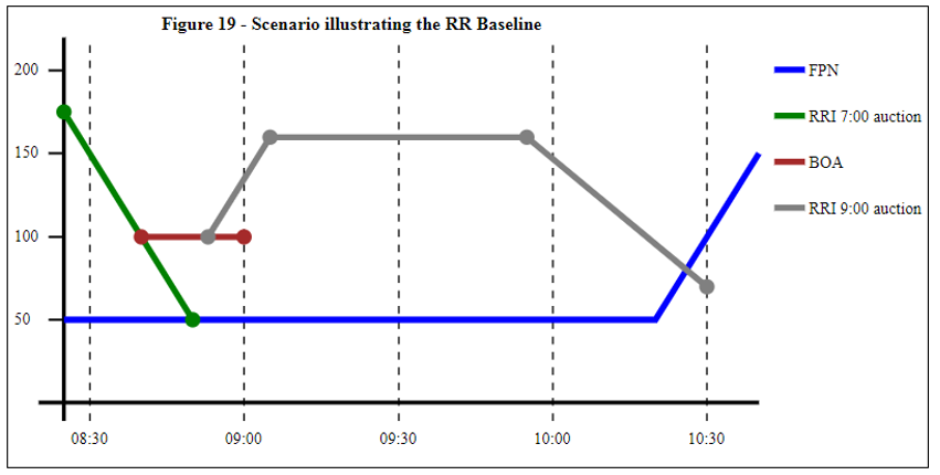
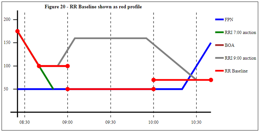
For example, Figure 19 illustrates the example of the hour H running from 09:00 to 10:00, where:
Gate Closure for the Auction Period is 08:05;
From 08:30 to 08:50 the BM Unit was running down from a previous RR Activation (relating to the 07:00 – 08:00 hour). The RR Instruction was issued at 06:32, and is therefore included in the RR Baseline for hour H; and
At 08:02 the NETSO issued a BOA, which is also included in the RR Baseline for Hour H; and
The RR Instruction (for the 09:00 – 10:00 hour) ramped down to a level of 70 MW
Figure 20 overleaf shows how the RR Baseline would be set in this instance:
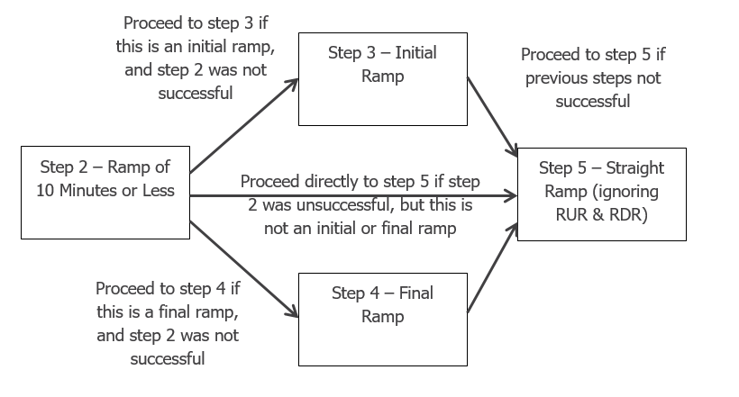
Having established the RR Baseline, steps 2 to 5 below are used to construct a ramp for each Quarter Hour boundary. Note that step 3 only applies to the initial ramp (from RR Baseline to the first non‑zero RRA of the Auction Period), and step 4 only applies to the final ramp (from the last non-zero RRA of the Auction Period back to RR Baseline). The path through these steps can therefore be summarised as follows:
3.3.2 Step 2 – Create Ramps of Ten Minutes or Less (where possible)
For each Quarter Hour boundary within the hour test whether it is possible to find a ramp of ten minutes duration (or less) that follows the declared Run-Up or Run-Down Rates.
For each boundary time t (where t = H, H+15, H+30, H+45 and H+60), the following candidate ramps are tested in turn, following the procedure in section 3.3.1 above. The notation ‘t+N’ means the point in time N minutes after time t:
Ramp from t–1 to t; or failing that t–1 to t+1
Ramp from t–2 to t+1; or failing that t–2 to t+2
Ramp from t–3 to t+2; or failing that t–3 to t+3
Ramp from t–4 to t+3; or failing that t–4 to t+4
Ramp from t–5 to t+4; or failing that t–5 to t+5
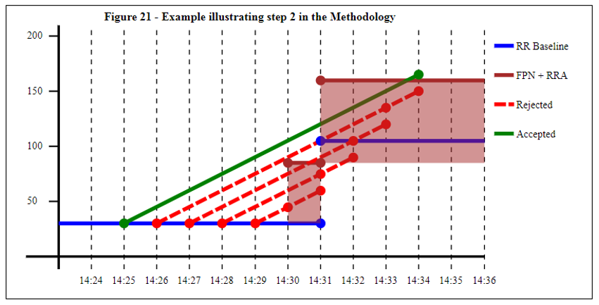
Figure 21 below illustrates this process:
The dotted red lines in Figure 21 are candidate profiles that are tested and rejected because they do not reach the required level by the end-point:
14:29 to 14:30 or 14:31;
14:28 to 14:31 or 14:32
14:27 to 14:32 or 14:33
14:26 to 14:33 or 14:34.
The solid green line is the first candidate tested (14:25 to 14:34) that does meet the required level (of FPN + RRA) by its end point (and would therefore be selected to form part of the RR Schedule).
As soon as a candidate is tested and found to work, no further candidates need be tested for that time t. If none of the ten candidates is found to work, proceed to step 3, 4 or 5.
3.3.3 Step 3 – Create An Initial Ramp of 11 to 30 minutes (where possible)
Identify the time t that is the start time of the first Quarter Hour in the Hour with a non-zero RRA. If step 2 did not successfully identify a ramp for this time t, the following additional candidates are tested in turn, following the procedure in section 3.3.1 above:
Ramp from t–6 to t+5
Ramp from t–7 to t+5
Ramp from t–25 to t+5
As soon as a candidate is tested and found to work, no further candidates need be tested for that time t. If none of the candidates is found to work, proceed to step 5.
3.3.4 Step 4 – Create A Final Ramp
Identify the time t that is the end time of the last Quarter Hour in the Hour with a non-zero RRA. If step 2 did not successfully identify a ramp for this time t, construct a ramp from t-5 using the procedure in section 3.3.1 above (with the maximum duration far in the future, to allow an unlimited ramp duration).
3.3.5 Step 5 – Create a straight ramp (without reference to Run-Up or Run-Down Rates)
For each time t (H, H+15, H+30, or H+45) where steps 2 to 4 failed to identify a workable ramp, create a straight line ramp (ignoring Run-Up Rates and Run-Down Rates). This results in a straight line profile joining the point (t0, y0) to (t1, y1) where:
y0 is the value of RRA + FPN if t0 is within the hour, or RR Baseline for times outside the hour;
t1 = t+5; and
y1 is the value of RRA + FPN if t1 is within the hour, or RR Baseline for times outside the hour.
3.3.6 Step 6 – Collate the RR Schedule
The RR Schedule is collated by combining:
The ramps created for each time t (H, H+15, H+30, H+45 and H+60) in steps 2 to 5; and
The values of FPN + RRA for all times t that are within the hour, but not included in any of the ramps.
4 PROCESS FOR AMENDING THIS METHODOLOGY
Section T1.14.2 of the BSC requires the BSC Panel to keep this document updated:
The Panel shall review the Replacement Reserve Schedule Methodology Document from time to time and in any event if there is a change to the Transmission Company’s requirements for the physical dispatch of a BM Unit to fulfil a Quarter Hour RR Activation, and shall make such revisions as it considers necessary.
For the purposes of BSC Procedure BSCP40 (Change Management) this document is a Category 3 BSC Configurable item, meaning that it is not subject to the Modification Procedures in Section F (‘Modification Procedures’) of the BSC, or the Change Proposal process described in BSCP40. The Panel has agreed the following process for changes:
It is the BSC Panel’s decision whether to review or change the Methodology, but BSCCo or the NETSO can request them to do so;
The BSC Panel may request assistance from BSCCo e.g. in analysing whether a change is needed; and
Unless otherwise agreed by the Panel, changes to the document will be drafted by BSCCo, and the Panel will consult with Parties in a manner appropriate to the scale and complexity of the change before agreeing them.
BSC Section T1.14.2 does not require a process for BSC Parties to propose changes to the RR Methodology, but ELEXON will always notify the BSC Panel of any concerns about the RR Methodology raised with the Panel Secretary (in writing) by a BSC Party, in order that the BSC Panel can make a decision on what action (if any) should be taken..
It should be noted that any material change to the Methodology will require changes to Settlement systems, and the BSC Panel would take this into account when agreeing the effective date for any change.
Examples of possible reasons for requesting a change to the Methodology include (but are not limited to):
A change to the NETSO’s dispatch principles;
A Party (or potential new entrant) raising concerns that there is an unjustified inconsistency between the Methodology and the NETSO’s dispatch principles; or
A Party (or potential new entrant) raising concerns that there the Methodology is having unintended and harmful consequences for competition in TERRE or the BM.
APPENDIX 1 – DEFINITIONS AND TERMS
The following table defines key terms used in this document:
Term | Definition |
“Balancing Energy Gate Closure Time” or “BEGCT” | The time of Gate Closure for a Replacement Reserve Auction Period. |
“Bid-Offer Acceptance” or “BOA” | Defined in the Grid Code. |
“Committed Level” or “CL” | Defined in the Grid Code. |
“Final Physical Notification” or “FPN” | Defined in Annex X-1 of the BSC. |
“Gate Closure” | Defined in Annex X-1 of the BSC. |
“Maximum Export Limit” or “MEL” | Defined in Annex X-2 of the BSC. |
“National Electricity Transmission System Operator” or “NETSO” | Defined in Annex X-1 of the BSC. |
“Quarter Hour RR Acceptance” | Defined in Annex X-1 of the BSC. |
“RR Activation” or “RRA” | Another term for “Quarter Hour RR Acceptance” |
“Replacement Reserve” or “RR” | Defined in Annex X-1 of the BSC. |
“Replacement Reserve Auction Period” | Defined in Annex X-1 of the BSC. |
“RR Baseline” | The baseline level, calculated in accordance with Step 1 of the RR Schedule Methodology (see section 3.3.1). It is intended to represent the MW profile that the BM Unit planned to follow (at Gate Closure for the Auction Period), in the absence of any subsequent RR Instructions or BOAs. See also Principles 3 and 7 (in section 2). |
“RR Instruction” | Defined in Annex X-1 of the BSC. |
“RR Schedule” | A profile of MW spot points deemed by the BMRA or SAA (in accordance with this Methodology) to represent the instruction that the National Electricity Transmission System Operator (NETSO) could have issued to a BM Unit in order to instruct it to deliver the results of each Replacement Reserve Auction. The RR Schedule may differ from the RR Instruction if BM Unit parameters declared by the Lead Party (or system conditions) prevent the NETSO from issuing the BM Unit with an instruction to deliver the results of the Replacement Reserve Auction. |
APPENDIX 2 – DETAILED LOGIC FOR TESTING CANDIDATE RAMP DURATION
This section provides a more formal description of the process described in section 3.2 above i.e. constructing a profile for the BM Unit to ramp up to the required level, starting at a time t0, and finishing by a time t1. This Appendix should be read in conjunction with the illustrative examples in section 3.2.
The process has one of two possible outcomes:
It may identify a MW profile that ramps up or down to the required level, in a manner consistent with the BM Unit’s declared Run-Up and Run-Down Rates; or
It may conclude that the ramp cannot be completed in this time (in which case the Methodology will go on to consider alternative options).
When constructing the final ramp, this procedure can be used with t1 set to an arbitrary time in the far future (to construct a ramp of unlimited duration).
STEP 1 – Determine the profile P(t) to which the ramp must be added
The first step is to determine the shape of the profile to which the ramp must be added. This profile is defined for times t (t0 <= t <= t1) as follows:
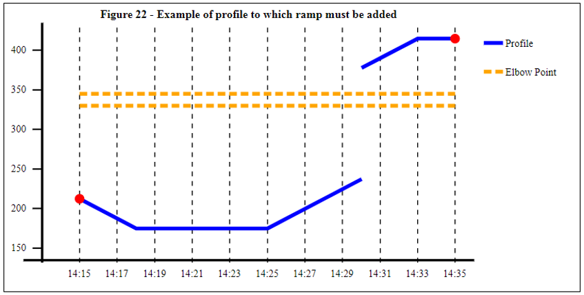
For example (referring back to the scenario illustrated in Figure 17), the profile to which the ramp must be added is shown by the blue line in Figure 21. The procedure in this Appendix must identify a ramp that starts at 14:15 and ramps up to re-meet the profile prior to 14:34, while respecting the declared Run-Up Rates:
Having identified the profile, determine its level y0 at t0, and y1 at t1 (using linear interpolation from the spot points defining the profile). At this stage these should be retained to a high level of accuracy (not rounded to a limited number of decimal places).
If there is a discontinuity (or ‘jump’) in the profile at time t0, the values of y0 and y1 should be determined in accordance with the rules in section 3.2.1 above. In the case where t0 is prior to the start of the Auction Period, this may require all remaining steps to be attempted for two different values of y0 (but if the first one tested allows the required ramp to be constructed successfully, the second option does not need to be considered).
The next step depends on whether the BM Unit is running up, or running down:
If y1 >= y0 the BM Unit is ramping up, and step 2A applies
If y1 < y0 the BM Unit is ramping down, and step 2B applies
STEP2A – Model an Upwards Ramp
This step creates the MW profile ramping upwards from the coordinates (t0, y0). It begins by identifying the relevant Run-Up Rates, which are:
The Run-Up Rate RUR0 applicable at y0; and
Run-Up Rates RURn (for n = 1, 2, 3…) associated with any Elbow Points En where En > y0
For each Elbow Point En (in increasing MW order), calculate the Elbow Point Time (EPTn) at which it will be reached.
EPTn = t0 + (En – y0) / RURn-1 (n=1)
EPTn = EPTn-1 + (En – En-1) / RURn-1 (n>1)
If EPTn > t1 (for any value n) it means enough of the upward ramp has been modelled, and no further values of EPTn need be calculated.
Calculate the MW level Y which will be reached at t1:
Y = EN + (t1 – EPTN) RURN (where N is the last elbow point for which EPTn was calculated); or
Y = y0 + (t1 – t0) RUR0 (if there are no elbow points)
STEP2B – Model a Downwards Ramp
This step creates the MW profile ramping downwards from the coordinates (t0, y0). It begins by identifying the relevant Run-Down Rates, which are:
The Run-Down Rate RDR0 applicable at y0; and
Run-Down Rates RDRn (for n = 1, 2, 3…) associated with any Elbow Points En where En < y0
For each Elbow Point En (in decreasing MW order), calculate the Elbow Point Time (EPTn) at which it will be reached:
EPTn = t0 + (y0 – En) / RDRn-1 (n=1)
EPTn = EPTn-1 + (En-1 – En) / RDRn-1 (n>1)
If EPTn > t1 (for any value n) it means enough of the upward ramp has been modelled, and no further values of EPTn need be calculated.
Calculate the MW level Y which will be reached at t1:
Y = EN – (t1 – EPTN) RDRN (where N is the last elbow point for which EPTn was calculated); or
Y = y0 – (t1 – t0) RDR0 (if there are no elbow points)
STEP 3 – Assess the candidate ramp
The output of Step 2A (or step 2B) is a MW profile ramping upwards (or downwards) as defined by the following points:
Table A2.1 - Spot points defining the ramp profile R(t) of the ramp |
Time | MW level |
t0 | y0 |
EPTn | En |
t1 | Y |
The next step is to assess this candidate ramp to determine whether it does meet the required level. There are three cases to consider, as shown in the following table:
No. | Scenario Description | Outcome of Process |
1. | We are not constructing a final ramp using Step 4 in the Methodology (see 3.3.4 above), and therefore the target time t1 is H+65 or less. The final value Y at t1 meets the required level (i.e. Y y1 for a ramp up, or Y ≤ y1 for a ramp down). | The candidate ramp duration can be accepted. The ramp profile to incorporate in the RR Schedule is as per Table A2.1 above, but with a final MW value of y1 (rather than Y). |
2. | We are not constructing a final ramp using Step 4 in the Methodology (see 3.3.4 above), and therefore the target time t1 is H+65 or less. The final value Y at t1 does not meet the required level (i.e. Y < y1 for a ramp up, or Y > y1 for a ramp down). | The candidate ramp duration does not meet the requirement, and can be rejected. |
3. | We are constructing a final ramp using Step 4 in the Methodology (see 3.3.4 above), and therefore the target time t1 is an arbitrary point in the future (t1 > H+65). | The ramp profile to incorporate in the RR Schedule is as per Table A2.1 above, but with the final point in the profile replaced with the time and MW level at which the ramp profile R(t) intersects the RR Baseline. Note that the RR Baseline is a constant value beyond H+60, and determining the point of intersection is therefore straightforward. |
In scenarios 1 and 3, an appropriate ramp has been identified. Round all times down to the earlier minute boundary, and all MW values to the nearest tenth of a MW (one decimal place).