CONTENTS
Constructing Aggregation Rules – Central Volume Allocation
Constructing Aggregation Rules – Central Volume Allocation |
Guidance Note |
What is an Aggregation Rule
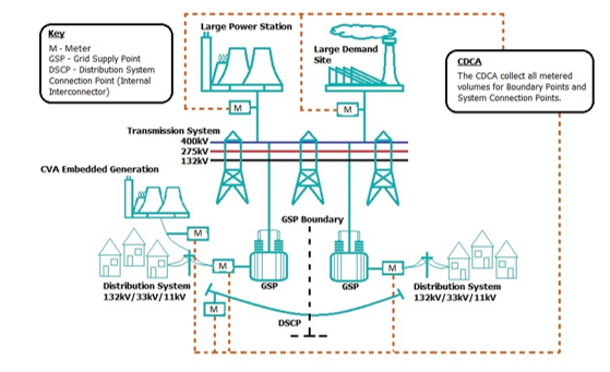
A Primary Balancing Mechanism Unit (Primary BM Unit) – either directly connected to the Transmission System or embedded within a Distribution System;
A Grid Supply Point (GSP);
A Distribution Systems Connection Point (DSCP) – also known as an Internal Interconnector;
A GSP Group; or
An External Interconnector (an interconnector to another country e.g. the Interconnector between England and France)
Export: AE > AI, therefore AE – AI is positive.
Import: AI > AE, therefore AE – AI is negative.
How to construct Aggregation Rules
For a Primary BM Unit the electrical single line diagram needs to show:
all of its proposed Boundary Point(s) to the Transmission and / or Distribution System;
all existing Boundary Points and any System Connection Points at or near the proposed Boundary Point(s); and
the location of the Metering Equipment6, in particular the Settlement current and voltage transformers (CTs/VTs).
For a GSP or DSCP the electrical single line diagram needs to show:
the proposed Systems Connection Points;
all existing or any other proposed Boundary Points and / or Systems Connection Points at or near the proposed Systems Connection Points; and
the location of the Metering Equipment6, in particular the Settlement current and voltage transformers (CTs/VTs).
BSCP20/4.3b Registration of Meter Technical Details Meter Register Details | |||||||||
Enter ‘*’ if data has changed | MSID: | 1234 | |||||||
Metering Subsystem ID | Meter Serial No. | Main / Check | Meter Register ID | Measurement Quantity ID (AI, AE, RI, or RE) | No of Register Dials | Meter Register Multiplier | Associated Meter ID | Associated Meter Register ID | |
* | STARM1 | CR097457 | Main | T1 | AI | 9 |
|
|
|
* | STARM1 | CR097457 | Main | T2 | AE | 9 |
|
|
|
* | STARM2 | CR097458 | Main | T1 | AI | 9 |
|
|
|
* | STARM2 | CR097458 | Main | T2 | AE | 9 |
|
|
|
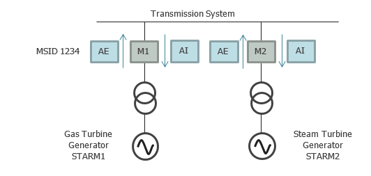
The MSID is 1234.
The VAU is STAR Generation and so the Metering Subsystem ID uses STAR and M1 representing Meter One or M2 representing Meter Two.
The Measurement Quantity IDs relevant to the Aggregation Rules are Active Export (AE) and Active Import (AI).
Aggregation Rules - BSCP75/4.2
Using the electrical single line diagram and the MTDs, you can write the Aggregation Rules.
Firstly, identify all the Boundary Points and / or Systems Connection Points on the electrical single line diagram, and the associated Metering Equipment. Aggregation Rules are of the form Active Export through the Meter at a Boundary Point minus Active Import. Where there is more than one Boundary Point associated with the VAU the net Energy is summed.
Then write out the algebraic expression to calculate the Energy through all Boundary Point(s) feeding into the Primary BM Unit. Star Generation would be as follows:
Total Volume = (Active Export through STAR Meter 1 - Active Import through STAR Meter 1) + (Active Export through STAR Meter 2 - Active Import through STAR Meter 2)
In an Aggregation Rule, the identifier for a specific line consists of the MSID, the Metering Subsystem ID (MSSID) and the Measurement Quantity (MQ) ID, i.e. MSID.MSSID.MQ
E.g. 1234.STARM1.AE
For Star Generation, the total volume in an algebraic expression would be
Total Metered Volume = (1234.STARM1.AE - 1234.STARM1.AI) + (1234.STARM2.AE - 1234.STARM2.AI)
Aggregation Rules are submitted on a BSCP75/4.2 form. The BSCP75/4.2 form requires the algebraic expression for your Aggregation Rule to be split out into single lines with one operation on each line. This is how the Aggregation Rule is entered into the CDCA System.
When the Aggregation Rule consists of more than one expression, the first line(s) of an Aggregation Rule should use the Expression Reference numbers of the following lines to highlight which lines are going to be used, so for Star generation, the BSCP75/4.2 form would be completed shown in figure 4:
BSCP75/4.2 | ||||||||||||||
Primary BM Unit (B) | √ | External Interconnector (I) |
| Internal Interconnector (D) |
| Grid Supply Point (P) |
| Grid Supply Point Group Take (G) |
| |||||
| ||||||||||||||
Aggregation Unit ID11 | T_STAR-1 | |||||||||||||
Aggregation Unit Name (optional) | STAR Generation | |||||||||||||
Effective From Date | 28/02/19 | |||||||||||||
Effective To Date (optional) |
| |||||||||||||
| ||||||||||||||
Expression Reference (ER) | MSQ, ER, BMU, GSP, DSCP, LLF or CST | Reference | +, -, /, x | MSQ, ER BMU, GSP, DSCP, LLF or CST | Reference | |||||||||
1 | ER | 2 | + | ER | 3 | |||||||||
2 | MSQ | 1234.STARM1.AE | - | MSQ | 1234.STARM1.AI | |||||||||
3 | MSQ | 1234.STARM2.AE | - | MSQ | 1234.STARM2.AI | |||||||||
Settlement Period x | M1 | M2 |
AE | 200MWh | 0MWh |
AI | 0MWh | 10MWh |
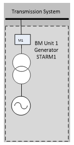
Worked Example - Single Transmission Connected Generation or Demand Primary BM Unit (T_Primary BM Unit)
BSCP20/4.3b Registration of Meter Technical Details Meter Register Details | |||||||||
Enter ‘*’ if data has changed | MSID: | 1234 | |||||||
Metering Subsystem ID | Meter Serial No. | Main / Check | Meter Register ID | Measurement Quantity ID (AI, AE, RI, or RE) | No of Register Dials | Meter Register Multiplier | Associated Meter ID | Associated Meter Register ID | |
* | STARM1 | CR097457 | Main | T1 | AI | 9 |
|
|
|
* | STARM1 | CR097457 | Main | T2 | AE | 9 |
|
|
|
BSCP75/4.2 | |||||
Expression Reference (ER) | MSQ, ER, BMU, GSP, DSCP, LLF or CST | Reference | +, -, /, x | MSQ, ER BMU, GSP, DSCP, LLF or CST | Reference |
1 | MSQ | 1234.STARTM1.AE | - | MSQ | 1234.STARTM1.AI |
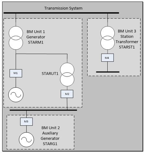
Worked Example – Transmission Connected Power Station with auxiliary Generation
BSCP20/4.3b Registration of Meter Technical Details Meter Register Details | |||||||||
Enter ‘*’ if data has changed | MSID: | 1234 | |||||||
Metering Subsystem ID | Meter Serial No. | Main / Check | Meter Register ID | Measurement Quantity ID (AI, AE, RI, or RE) | No of Register Dials | Meter Register Multiplier | Associated Meter ID | Associated Meter Register ID | |
* | STARM1 | CR097457 | Main | T1 | AI | 9 |
|
|
|
* | STARM1 | CR097457 | Main | T2 | AE | 9 |
|
|
|
* | STARUT1 | CR097458 | Main | T1 | AI | 9 |
|
|
|
* | STARUT1 | CR097458 | Main | T2 | AE | 9 |
|
|
|
* | STARG1 | CR097459 | Main | T1 | AI | 9 |
|
|
|
* | STARG1 | CR097459 | Main | T2 | AE | 9 |
|
|
|
* | STARST1 | CR097460 | Main | T1 | AI | 9 |
|
|
|
* | STARST1 | CR097460 | Main | T2 | AE | 9 |
|
|
|
BSCP75/4.2 | |||||
Expression Reference (ER) | MSQ, ER, BMU, GSP, DSCP, LLF or CST | Reference | +, -, /, x | MSQ, ER BMU, GSP, DSCP, LLF or CST | Reference |
1 | ER | 2 | - | ER | 5 |
2 | ER | 3 | + | ER | 4 |
3 | MSQ | 1234.STARM1.AE | - | MSQ | 1234.STARM1.AI |
4 | MSQ | 1234.STARUT1.AE | - | MSQ | 1234.STARUT1.AI |
5 | MSQ | 1234.STARG1.AE | - | MSQ | 1234.STARG1.AI |
BSCP75/4.2 | |||||
Expression Reference (ER) | MSQ, ER, BMU, GSP, DSCP, LLF or CST | Reference | +, -, /, x | MSQ, ER BMU, GSP, DSCP, LLF or CST | Reference |
1 | MSQ | 1234.STARG1.AE | - | MSQ | 1234.STARG1.AI |
BSCP75/4.2 | |||||
Expression Reference (ER) | MSQ, ER, BMU, GSP, DSCP, LLF or CST | Reference | +, -, /, x | MSQ, ER BMU, GSP, DSCP, LLF or CST | Reference |
1 | MSQ | 1234.STARST1.AE | - | MSQ | 1234.STARST1.AI |
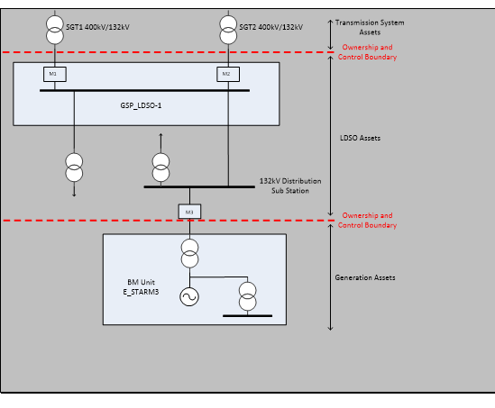
Worked Example – Distribution Connected Primary BM Unit (E_Primary BM Unit)
BSCP20/4.3b Registration of Meter Technical Details Meter Register Details | |||||||||
Enter ‘*’ if data has changed | MSID: | 1234 | |||||||
Metering Subsystem ID | Meter Serial No. | Main / Check | Meter Register ID | Measurement Quantity ID (AI, AE, RI, or RE) | No of Register Dials | Meter Register Multiplier | Associated Meter ID | Associated Meter Register ID | |
* | STARM3 | CR097459 | Main | T1 | AI | 9 |
|
|
|
* | STARM3 | CR097459 | Main | T2 | AE | 9 |
|
|
|
BSCP75/4.2 | |||||
Expression Reference (ER) | MSQ, ER, BMU, GSP, DSCP, LLF or CST | Reference | +, -, /, x | MSQ, ER BMU, GSP, DSCP, LLF or CST | Reference |
1 | ER | 2 | - | ER | 3 |
2 | MSQ | 1234.STARM3.AE | x | LLF |
|
3 | MSQ | 1234.STARM3.AI | x | LLF |
|
BSCP20/4.3b Registration of Meter Technical Details Meter Register Details | |||||||||
Enter ‘*’ if data has changed | MSID: | 1234 | |||||||
Metering Subsystem ID | Meter Serial No. | Main / Check | Meter Register ID | Measurement Quantity ID (AI, AE, RI, or RE) | No of Register Dials | Meter Register Multiplier | Associated Meter ID | Associated Meter Register ID | |
* | STARM3 | CR097459 | Main | T1 | AI | 9 |
|
|
|
BSCP20/4.3b Registration of Meter Technical Details Meter Register Details | |||||||||
Enter ‘*’ if data has changed | MSID: | 1235 | |||||||
Metering Subsystem ID | Meter Serial No. | Main / Check | Meter Register ID | Measurement Quantity ID (AI, AE, RI, or RE) | No of Register Dials | Meter Register Multiplier | Associated Meter ID | Associated Meter Register ID | |
* | STARM3 | CR097459 | Main | T2 | AE | 9 |
|
|
|
BSCP75/4.2 | |||||
Expression Reference (ER) | MSQ, ER, BMU, GSP, DSCP, LLF or CST | Reference | +, -, /, x | MSQ, ER BMU, GSP, DSCP, LLF or CST | Reference |
1 | ER | 2 | - | ER | 3 |
2 | MSQ | 1235.STARM3.AE | x | LLF |
|
3 | MSQ | 1234.STARM3.AI | x | LLF |
|
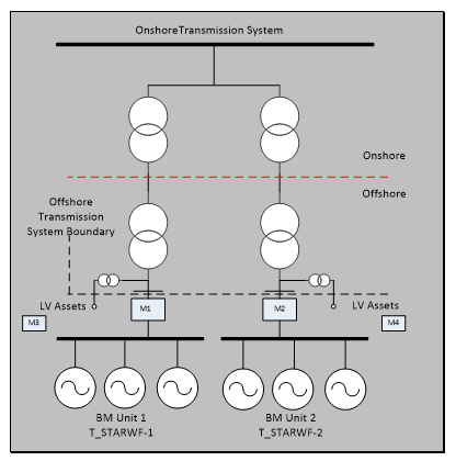
Worked Example - Offshore Wind Farm
BSCP20/4.3b Registration of Meter Technical Details Meter Register Details | |||||||||
Enter ‘*’ if data has changed | MSID: | 1234 | |||||||
Metering Subsystem ID | Meter Serial No. | Main / Check | Meter Register ID | Measurement Quantity ID (AI, AE, RI, or RE) | No of Register Dials | Meter Register Multiplier | Associated Meter ID | Associated Meter Register ID | |
* | STARWFM1 | CR097457 | Main | T1 | AI | 9 |
|
|
|
* | STARWFM1 | CR097457 | Main | T2 | AE | 9 |
|
|
|
* | STARWFM2 | CR097458 | Main | T1 | AI | 9 |
|
|
|
* | STARWFM2 | CR097458 | Main | T2 | AE | 9 |
|
|
|
* | STARLVM3 | CR097459 | Main | T1 | AI | 9 |
|
|
|
* | STARLVM3 | CR097459 | Main | T2 | AE | 9 |
|
|
|
* | STARLVM4 | CR097460 | Main | T1 | AI | 9 |
|
|
|
* | STARLVM4 | CR097460 | Main | T2 | AE | 9 |
|
|
|
BSCP75/4.2 | |||||
Expression Reference (ER) | MSQ, ER, BMU, GSP, DSCP, LLF or CST | Reference | +, -, /, x | MSQ, ER BMU, GSP, DSCP, LLF or CST | Reference |
1 | ER | 2 | + | ER | 3 |
2 | MSQ | 1234.STARWFM1.AE | - | MSQ | 1234.STARWFM1.AI |
3 | MSQ | 1234.STARLVM3.AE | - | MSQ | 1234.STARMLVM3.AI |
BSCP75/4.2 | |||||
Expression Reference (ER) | MSQ, ER, BMU, GSP, DSCP, LLF or CST | Reference | +, -, /, x | MSQ, ER BMU, GSP, DSCP, LLF or CST | Reference |
1 | ER | 2 | + | ER | 3 |
2 | MSQ | 1234.STARWFM2.AE | - | MSQ | 1234.STARWFM2.AI |
3 | MSQ | 1234.STARLVM4.AE | - | MSQ | 1234.STARMLVM4.AI |
Worked Example - GSP – Grid Supply Point Single LDSO
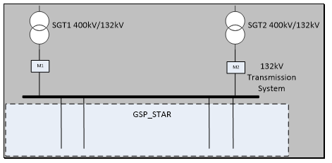
BSCP20/4.3b Registration of Meter Technical Details Meter Register Details | |||||||||
Enter ‘*’ if data has changed | MSID: | 1234 | |||||||
Metering Subsystem ID | Meter Serial No. | Main / Check | Meter Register ID | Measurement Quantity ID (AI, AE, RI, or RE) | No of Register Dials | Meter Register Multiplier | Associated Meter ID | Associated Meter Register ID | |
* | STARSGT1 | CR097459 | Main | T1 | AI | 9 |
|
|
|
* | STARSGT1 | CR097459 | Main | T2 | AE | 9 |
|
|
|
* | STARSGT2 | CR097460 | Main | T1 | AI | 9 |
|
|
|
* | STARSGT2 | CR097460 | Main | T2 | AE | 9 |
|
|
|
BSCP75/4.2 | |||||
Expression Reference (ER) | MSQ, ER, BMU, GSP, DSCP, LLF or CST | Reference | +, -, /, x | MSQ, ER BMU, GSP, DSCP, LLF or CST | Reference |
1 | ER | 2 | + | ER | 3 |
2 | MSQ | 1234.STARSGT1.AE | - | MSQ | 1234.STARSGT1.AI |
3 | MSQ | 1234.STARSGT2.AE | - | MSQ | 1234.STARSGT2.AI |
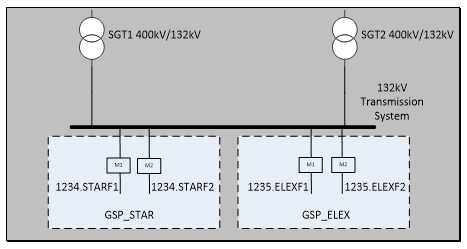
Worked Example - GSP – Shared Grid Supply Point
BSCP20/4.3b Registration of Meter Technical Details Meter Register Details | |||||||||
Enter ‘*’ if data has changed | MSID: | 1234 | |||||||
Metering Subsystem ID | Meter Serial No. | Main / Check | Meter Register ID | Measurement Quantity ID (AI, AE, RI, or RE) | No of Register Dials | Meter Register Multiplier | Associated Meter ID | Associated Meter Register ID | |
* | STARF1 | CR097459 | Main | T1 | AI | 9 |
|
|
|
* | STARF1 | CR097459 | Main | T2 | AE | 9 |
|
|
|
* | STARF2 | CR097460 | Main | T1 | AI | 9 |
|
|
|
* | STARF2 | CR097460 | Main | T2 | AE | 9 |
|
|
|
BSCP75/4.2 | |||||
Expression Reference (ER) | MSQ, ER, BMU, GSP, DSCP, LLF or CST | Reference | +, -, /, x | MSQ, ER BMU, GSP, DSCP, LLF or CST | Reference |
1 | ER | 2 | + | ER | 3 |
2 | MSQ | 1234.STARF1.AE | - | MSQ | 1234.STARF1.AI |
3 | MSQ | 1234.STARF2.AE | - | MSQ | 1234.STARF2.AI |
BSCP75/4.2 | |||||
Expression Reference (ER) | MSQ, ER, BMU, GSP, DSCP, LLF or CST | Reference | +, -, /, x | MSQ, ER BMU, GSP, DSCP, LLF or CST | Reference |
1 | ER | 2 | + | ER | 3 |
2 | MSQ | 1235.ELEXF1.AE | - | MSQ | 1235.ELEXF1.AI |
3 | MSQ | 1235.ELEXF2.AE | - | MSQ | 1235.ELEXF2.AI |
Worked Example - Distribution System Connection Point – DSCP
BSCP20/4.3b Registration of Meter Technical Details Meter Register Details | |||||||||
Enter ‘*’ if data has changed | MSID: | 1236 | |||||||
Metering Subsystem ID | Meter Serial No. | Main / Check | Meter Register ID | Measurement Quantity ID (AI, AE, RI, or RE) | No of Register Dials | Meter Register Multiplier | Associated Meter ID | Associated Meter Register ID | |
* | ELEX5 | CR097460 | Main | T1 | AI | 9 |
|
|
|
* | ELEX5 | CR097460 | Main | T2 | AE | 9 |
|
|
|
BSCP75/4.2 | |||||
Expression Reference (ER) | MSQ, ER, BMU, GSP, DSCP, LLF or CST | Reference | +, -, /, x | MSQ, ER BMU, GSP, DSCP, LLF or CST | Reference |
1 | ER | 2 | + | ER | 3 |
2 | MSQ | 1236.ELEX5.AE | x | LLF |
|
3 | MSQ | 1236.ELEX5.AE | x | LLF |
|
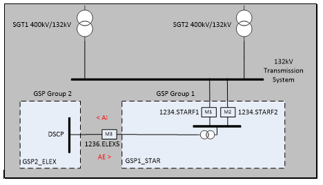
GSP Group Take Aggregation Rules
The registration or de-registration of a GSP (note that this does not include the registration or de-registration of individual circuits at the GSP)
The registration or de-registration of an Embedded Primary BM Unit (or Distribution connected circuits that are part of an M_ cascade hydro Primary BM Unit) with a CVA registered Metering System
The registration or de-registration of a DSCP (note that this does not include the registration or de-registration of individual circuits at the DSCP). This will require changes to two sets of GSP Group Take Aggregation Rules for the two GSP Groups that the DSCP is connecting. The normal convention is that DSCP aggregated volumes (i.e. normal flow AI to the ‘Host’ LDSO’s GSP Group) will be ADDED (+II) to the ‘Host’ LDSO’s GSP Group Take Aggregation Rule, and SUBTRACTED (-II) from the ‘Other’ LDSO’s GSP Group Take Aggregation Rule (i.e. normal flow AE from the ‘Other’ LDSO’s GSP Group).
CDCA Constraints & System Parameters for Aggregation Rules
CDCA system rounds all Metered Volumes in the CDCA database to 4 decimal places only (i.e. 0.00009 or smaller will not be output as a result of a mathematical calculation), using the normal rounding rules. Constants (CST) can be up to 5 decimal places, but are still subject to the above rounding.
Do not leave blank rows in the middle of the Aggregation Rule table.
Make the Expression References (ER) as sequential as possible (for example, DO NOT use ER 1 + ER 9, ER 2 + ER 8 etc. instead use sequential numbering ER 1 + ER 2, ER 3 + ER 4 etc.) This allows the Aggregation Rule to be entered into CDCA more logically.
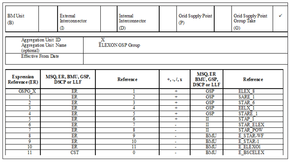
CDCA does not support the expression of a negative first term in an Aggregation Rule, so where IMPORT ONLY is being aggregated, it should be written as either as CST 0 – MSQ 1234.STARSGT1.AI, or MSQ 1234.STARSGT1.AI * CST -1. CST represents a constant.
A LLF can only be applied in CDCA at the MSID level, NOT at the channel level. Because of this, the same LLF would be applied to both the AE & AI metered data. If this is not correct, then an additional LLF is required, which would require an additional MSID.
Parameters for Aggregation Rules:
Intellectual Property Rights, Copyright and Disclaimer The copyright and other intellectual property rights in this document are vested in Elexon or appear with the consent of the copyright owner. These materials are made available for you for the purposes of your participation in the electricity industry. If you have an interest in the electricity industry, you may view, download, copy, distribute, modify, transmit, publish, sell or create derivative works (in whatever format) from this document or in other cases use for personal academic or other non-commercial purposes. All copyright and other proprietary notices contained in the document must be retained on any copy you make. All other rights of the copyright owner not expressly dealt with above are reserved. No representation, warranty or guarantee is made that the information in this document is accurate or complete. While care is taken in the collection and provision of this information, Elexon Limited shall not be liable for any errors, omissions, misstatements or mistakes in any information or damages resulting from the use of this information or action taken in reliance on it. |
1 A CVA Boundary Point is a Boundary Point where Imports and Exports are measured by CVA Meters System(s). Often this connection between the Transmission System and a Generation or Demand Primary BM Unit but can also be Generation measured by a CVA Metering System which is connected to the Distribution System.
2 A Systems Connection Point is a connection between the Transmission System and a Distribution System or between two Distribution Systems.
3 A Metering System is a set of particular commissioned Metering Equipment installed for the purposes of measuring the quantities of Imports/Exports at Boundary Points to the Total System or flows of electricity at Systems Connection Points.
4 A Meter Register means a device, normally associated with a Meter, from which it is possible to obtain a reading of the amount of Active Energy, or the amount of Reactive Energy that has been supplied by a circuit.
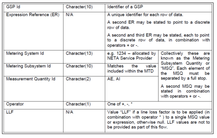
5 An MSID is a unique number for a Metering System supplied by the CRA.
6 Metering Equipment means Meters, measurement transformers (voltage, current or combination units), metering protection equipment including alarms, circuitry, associated Communications Equipment and Outstations and wiring.
7 Settlement Period means a period of 30 minutes beginning on the hour or the half-hour and in accordance with BSC Annex X-2 paragraph 4.3.
8 A Meter Register ID is limited in the BSCP20/4.3 form to two characters in length and must be unique within a Meter.
9 A Metering Subsystem ID should have some reference to the actual VAU for example the VAU name abbreviation (e.g. VAU: STAR Generation, Metering Subsystem ID: STAR. It is limited to 10 alphanumeric characters.
10 Measurement Qualities are Active Export (AE), Active Import (AI), Reactive Export (RE), Reactive Import (RI) or Undefined (UN).
11 The Aggregation Unit ID is the VAU ID, i.e the Primary BM Unit ID, the Interconnector Name, the DSCP ID, the GSP ID or the GSP Group ID.
12 In this example, the GSP is ‘shared’ between two LDSOs, but a shared GSP can also be one where there is a GSP and directly connected generator or demand connected to the same busbar.