Advanced Search

Code of Practice Four

v 8.0
Download

Code of Practice Four

Guidance Note

Code of Practice 4

This guidance will help Registrants and CVA and SVA Meter Operator Agents (MOAs) to meet some of the requirements of Code of Practice 4.

Commissioning

What is Half Hourly Commissioning?

Commissioning is a series of site tests and checks used to demonstrate that Metering Equipment complies with the relevant metering Code of Practice (CoP). Before Commissioning tests occur, you need to calibrate the individual items of Metering Equipment that make up the Metering System. If you identify failures to meet the relevant CoP during Commissioning, you need to address these before the end of the Commissioning tests. Where a MOA identifies failures in relation to the measurement transformers the MOA shall inform the Registrant.

This section sets out those tests and checks that may be used in the Commissioning procedure for new installations. Where the Metering System has changed (or individual items of Metering Equipment have changed) then you only need to perform the tests and checks to confirm the Overall Accuracy of the Metering System.

Who is responsible for Commissioning?

The Registrant of the Metering System is responsible for ensuring all Metering Equipment is Commissioned and appoints an MOA to ensure Commissioning is complete and that overall accuracy is maintained in accordance with the relevant CoP. In some cases, it is necessary for Commissioning tests to be conducted, and Commissioning records produced, by someone other than the MOA. Since the implementation of Modification Proposal P283 on 6 November 2014 the responsibility for Commissioning new measurement transformers (in accordance with CoP4) will sit with the Equipment Owner, where they are a BSC Party (e.g. the Distribution or National Electricity Transmission System Operator (NETSO)). Where the Equipment Owner is not a BSC Party (e.g. a Customer of a Supplier) then the responsibility will remain with the Registrant. For the avoidance of doubt, where measurement transformers are to be adopted into a BSC Party’s ownership at a later date (such as those installed by Independent Connection Providers (ICPs), then that BSC Party will be responsible for Commissioning of those measurement transformers following adoption or energisation of the Metering System comprising the measurement transformers. Where this document refers to measurement transformers owned by a BSCP Party, that definition shall be taken to include those measurement transformers which are to be adopted at a later date.

It is up to the appointed MOA to ensure that all Commissioning is carried out in accordance with CoP4. In this guidance note, we refer to the organisation conducting Commissioning as the ‘Commissioning organisation’. Under P283, where the MOA identifies that the Commissioning of the measurement transformers is incomplete or incorrect then the MOA shall inform the Registrant of the omission or error and provide a view on the risk the omission or error poses to Settlement. The Registrant will then need to liaise with the Equipment Owner to determine what to do to address the omission or error. Further information regarding responsibility can be found in the P283 guidance, ‘Commissioning of Measurement Transformers for Settlement purposes’.

This guidance relates to Issue 6 of Code of Practice 4

What does the Commissioning organisation do?

The scope of checks and tests listed below are guidance for achieving the minimum requirements. The Commissioning organisation needs to produce detailed procedures, which should include these requirements. You then record the test equipment details and serial numbers, plus the results of the checks and tests, on these procedures and keep them for future reference/audit.

You need to keep the results of the checks and tests until the Meter is replaced or scrapped or, if you make primary current measurements, then you’ll need to keep the results for as long as necessary for proving/confirming measurement transformer connected ratios for future reference/audit.

You may also need to perform basic tests on earthing, insulation, continuity, etc., on your Metering Equipment. You need to perform these in accordance with Good Industry Practice.

Who is responsible for safety?

The Commissioning organisation is responsible for safe working methods.

Once the tests start, you should secure all Metering Equipment to prevent anyone other than an authorised operative of the appointed MOA or Licenced Distribution System Operator (LDSO) from accessing it.

What do I do with dual-ratio / multi-ratio measurement transformers?

We suggest, wherever possible and practical, you test and prove the ratios that will become the spare/other ratios for future use (e.g. to cater for load increase, etc.); you need to do the final Commissioning tests on the actual connected ratio. At the end of the tests, you need to secure access to the ratio-selection/all Metering Equipment to prevent unauthorised access to the equipment.

Scope of the Commissioning Tests

On site Commissioning tests are used to confirm and record:

    • The current transformers are of the correct ratio, phase and polarity;

    • The current transformers are correctly located to record the required power flow;

    • The voltage transformers are the correct ratio and phase;

    • The voltage transformers are correctly located to record the required voltage;

    • The burdens on the measurement transformers are within the correct limits;

    • The Meters are set to the same current transformer and voltage transformer ratios as the installed measurement transformers;

    • The Meters have the correct Compensation (e.g. for errors in the measurement transformers/connections and losses in power transformers1 ), where appropriate;

    • The Metering System correctly records the energy at the Defined Metering Point;

    • Phase rotation is standard at the Meter;

    • The operation of the test terminal block; and

    • Half Hourly Metering Equipment detects phase failure and operates the required alarms.

I’m the Commissioning organisation. What should I do?

The next section is for the Commissioning organisation and it shows you how to achieve the minimum requirements above.

You need to test Central Volume Allocation (CVA) Metering Equipment before energisation. At this point, you need to record sufficient evidence to confirm the Overall Accuracy of the Metering System is within limits of the relevant Code of Practice.

For Supplier Volume Allocation (SVA) Metering Equipment you can test them with the system energised or de-energised. You need to record evidence of Overall Accuracy either before or after energisation.

Inspection/Tests

The following checklist will help you with testing:

    • Check the Metering System is complete and that it won’t be changed after the Commissioning tests are performed.

    • Record nameplate details from the measurement transformers, Meters, Outstations (where separate from the Meter) and metering protection equipment.

    • Check that measurement transformers and Meters have Calibration Certificates for the correct Class and that the serial numbers match. Check that Meter Compensation information is included with the Meter Calibration Certificate.

    • Check any auxiliary supplies to the Metering Equipment are available and are the correct voltage.

    • Check the settings to any metering protection equipment and ensure discrimination between protection equipment, i.e. lowest rating nearest the Meter/Metering Equipment.

    • Confirm the correct operation of the local interrogation facility (Meter or Outstation).

    • Check the external communications to the Meter/Outstation are functioning and are in accordance with the Meter Technical Details (MTDs) (where required2 ).

Installation Data

Has all the standing data including passwords been programmed into the Meter and Outstation and is the Outstation clock is set to Co-ordinated Universal Time (UTC)?

Check the channel allocation against the MTDs.

Proving Measurement Transformer Ratios

Where practical you should do the tests listed below. Where the primary plant isn’t accessible or where the tests are meaningless, for instance on a high voltage measurement transformer, these tests may not be possible.

If tests are not performed you should record the reason and perform live Commissioning tests to confirm ratio, phasing and polarity.

Current Transformers

    • Inject each primary current transformer in turn and check that secondary current is passing through the Meter and the test terminal block(s).

    • Record the primary and secondary currents.

    • Check the current transformer ratio against the Meter Technical Details.

    • Carry out direct current flick tests to establish polarity.

Voltage Transformers

    • For polyphase3 voltage transformers, inject two or three phase voltages onto the primary of the voltage transformer (400V or 230V is usually adequate).

    • Record primary and secondary voltages and phase rotation at the Meter and the test terminal block(s).

    • Where voltage transformer neutral connections are available, inject single phase from each primary phase to neutral and record the secondary phase to neutral voltages.

    • Then calculate, record and check the voltage transformer ratio against the Meter Technical Details.

Burden Tests

Next, you need to test that the measurement transformers won’t be overburdened even at full load by carrying out a burden test.

The following tests are examples of burden tests. There are other ways to check burden ratings.

    • Inject current as close as is practical to the measurement transformers to establish and record the burden on the current transformers and voltage transformers.

    • Where primary injection has not been performed check that current and voltage is present at the Meter and the test terminal block(s).

    • Check that the burden ratings are within the normal operating range of the measurement transformers.

    • Where burden values are used to compensate the Meter, check that any estimated values are accurate.

    • Record the value of burdens (including any non-Settlement burdens) necessary to provide evidence of the overall metering accuracy.

You can also use resistance measurements to check the burden rating.

Secondary Injection Tests

    • Inject current and voltage from the test terminal block(s) into the Meter at the rated values.

    • Check that the injected energy matches all the outputs of the Meter, which may (when fitted) include test Light Emitting Diodes (LEDs), dials, pulse outputs and communication port data.

    • Where there are separate Outstations installed, check that energy injected is correctly recorded by the Outstation.

You need to inject enough energy to provide meaningful results. You would normally do this over a half-hour period. All the values will be recorded at the start and finish of the test and compared against the expected results (to include Compensation where appropriate). This test should be repeated to cover all measurement quantities of the Meter i.e. Import, Export, Active and Reactive Energy. It can also be used in conjunction with the proving tests, see BSCP02: Proving Test Requirements for Central Volume Allocation Metering Systems or BSCP514: SVA Meter Operations for Metering Systems Registered in SMRS.

Phase Failure Detection Tests

Use this test to confirm that the phase fail detection equipment works:

    • For CVA, inject any installed metering protection equipment, e.g. voltage transformer phase failure or phase unbalance equipment. Check for correct settings and monitor the local and remote alarms.

    • For SVA, carry out tests to confirm the correct operation of Meter voltage failure indicators.

Commissioning Tests with the System Live

When the Meter is first energised, perform these tests. Check that the Meter is energised and recording energy in the correct quadrant.

For CVA

    • Carry out a prevailing load check by measuring the energy at the test terminals against the recorded energy at the Meter. Confirm that the main and check Meters are recording identical values of energy.

    • Verify the phase sequence of the metering voltage transformer secondary connections against another known voltage transformer connected to the same source. Confirm the ratio of the voltage transformer by comparison.

    • Measure the metering current transformer secondary current and compare with the secondary current from an independent current transformer, which has its primary connected in series with the metering current transformer. You can use a current clamp meter for this test. This test is used to confirm that the correct current transformer tap was selected. These values should be within 10% of each other.

Where a separate measurement of energy is available (this could be a test energy meter or even a power indicator for a steady load) which is independent of the metering current transformers and voltage transformers on the circuit, then you could do a comparison over a half-hour period and record the results. This is not an accuracy check; it will confirm the overall system is of the right order. These values should be within 10% of each other.

Where protection measurement transformers with their primaries connected in series with the metering measurement transformers or dual-purpose metering/protection measurement transformers (separate windings on the same core) are available, where practical, measure and compare the secondary current to prove the connected ratio.

For SVA

Carry out a prevailing load check by measuring the primary4 , secondary and Meter energy values and compare them against each other. These values should be within 10% of each other.

For both CVA and SVA

    • Carry out a phase rotation test at the test terminal block(s) and the Meter. The Meter must be standard phase rotation.

    • Where possible, confirm that the Meter is recording similar current and voltage values to primary or secondary load.

    • Carry out a test to confirm the operation of the test terminal block(s).

At the end of all the tests you should record enough information to demonstrate that the Overall Accuracy of the Metering System is within the limits of the relevant Code of Practice.

Records

At the end of all the tests you should record enough information to demonstrate that the Overall Accuracy of the Metering System is within the limits of the relevant Code of Practice (see ‘Overall Accuracy’). Both Meter and Outstation readings for Settlement channels need to be recorded. See section 5.5.4 of Code of Practice 4 for information on what minimum evidence you need to contain in your records.

Measurement Uncertainty

What is Measurement Uncertainty?

This section explains that there is a degree of uncertainty associated with any measurement. This is just a high level overview of this area and you can read more information about it in the UKAS document, M3003 ‘The Expression of Uncertainty and Confidence in Measurement’.

There are a range of factors, in both type and effect, which contribute to measurement uncertainty. It’s important to take all of these factors into account when dealing with Settlement metering accuracy. In some cases, you may conclude that certain factors have no material bearing on measurement and therefore you can regard its effect as negligible.

For example: the measurement of an electrical load is recorded by an instrument which has a stated error of ±2% at a temperature of 20°C. The instrument is connected to a circuit and records 50.5kW at an ambient temperature of 22°C.

Two factors will affect the example above. First, the accuracy of measurement and second, any influencing factor (in this case the effects of temperature). The instrument recorded 50.5kW which has an error of ±2%. Therefore the actual load is between 49.49kW and 51.51kW.

The second factor (or influencing quantity) is temperature. There is a 2°C discrepancy between the stated performance of the instrument and the ambient temperature at the time it’s measured. However, there is no information that would indicate the net effect of this temperature discrepancy. In practice the stated ±2% inaccuracy of the instrument will become greater either side of 20°C, e.g. ±0.2%/ °C. This means the actual load will be 50.5kW ±2.4%, or between 49.29kW and 51.71kW.

Other influencing quantities will also affect the accuracy of measurement such as frequency variation, relative humidity and stray electromagnetic fields. You need to consider each carefully.

We suggest that measurement uncertainty should include the following:

Overall uncertainty = Calibration Equipment uncertainty + uncertainty due to (temp + frequency + relative humidity + operator errors, etc.).

What do we mean by repeatability?

You can repeat tests. This will help you see whether there are any influencing factors that change significantly to affect the readings. You need to minimise these factors to get reliable test results.

For example, if you repeat a test several times and the measurements are recorded from an analogue instrument, you could find that the results differ. This could be because the position you take the tests from differs for each test (Parallax). One way to eliminate this influencing factor (operator error) is to take the measurements from the same position each time.

How to limit influencing factors

If you need to measure a load of 50kW to an accuracy of ±2%, then you have to do this with a class 2 instrument when there are no other factors to take into account.

You could select an instrument of greater accuracy (say ±1%) which will provide ‘room’ for the factors of uncertainty. In the worked example given earlier, the overall inaccuracy of measurement would become ±1.4%; i.e. well within the required ±2%. Selecting this instrument of ±1% accuracy allows for an uncertainty budget of 1%.

Generally, influencing factors are relatively predictable and with respect to a measurement standard of ±2%, are usually quite small. However, with greater accuracy requirements such as for CoPs 1 and 2 these factors become more significant as the uncertainty budget becomes a larger proportion of the overall measurement.

To confirm whether a Meter is performing to CoP1 accuracy standards (predominantly ±0.2%) the combined uncertainty of measurement may be higher than the required accuracy. Testing these Meters with an instrument that has an accuracy of ±0.1% leaves only 0.1% for the influencing factors where the temperature discrepancy alone may account for this whole budget.

In which case, the only option is to eliminate as many uncertainties as possible by doing the tests under very controlled conditions such as in a laboratory.

Overall Accuracy

What is Overall Accuracy?

The CoPs set out the accuracy requirements (or limits of measurement error), for Active and Reactive Energy measurements at various current and power factor conditions for Metering Systems (see section 4.3 ‘Accuracy Requirements’ of CoPs 1, 2, 3 and 5). The limits specified in the CoPs refer to energy measurements at, or referred to, the Defined Metering Point (DMP). If where the measurement of energy is carried out (the Actual Metering Point (AMP)) is not at the DMP, then you need to apply for a Metering Dispensation. In this case, you may need to take Compensation into account when calculating the Overall Accuracy (referred to the DMP) of the Metering System (see section 4.3.3 ‘Compensation for Power Transformer and Line Losses’ of CoPs 1, 2, 3 and 5)5 .

You need to consider three main factors when calculating Overall Accuracy to ensure that the Overall Accuracy of the Metering System is within the limits of measurement error defined in the relevant CoP, at the DMP.

These include:

    • The measurement errors associated with the individual items of Metering Equipment that make up the Metering System (including the measurement uncertainty associated with the measured values obtained through their Calibration);

    • Any measurement error contributions due to the connections between each item of Metering Equipment (e.g. leads connecting measurement transformers to the Meter); and

    • Compensation that has been deliberately added to the Meter to account for:

      • any measurement error due to the AMP not being at the DMP (i.e. for Power Transformer and Line Losses); and/or

      • measurement errors associated with measurement transformers (see section 4.3.2 ‘Compensation for Measurement Transformer Error’ of CoPs 1, 2, 3 and 5).

A Metering System may be composed of various items of Metering Equipment; e.g. Meters, measurement transformers (voltage, current or combination units), metering protection equipment (including alarms), circuitry associated with Communications Equipment and Outstations and wiring. You need to consider the individual measurement error contributions of these items when determining the Overall Accuracy of the Metering System.

In addition, since you can never exactly know the error determined for an individual item, each measured error value obtained through Calibration will have an associated measurement uncertainty. For example, at Unity Power Factor (UPF), under reference conditions and at 10% rated current, the measurement error of a particular current transformer winding is +0.4% +/- 0.1, i.e. there is a probability (approximately 95% if the coverage factor, k = 26 ) that the actual measurement error will lie somewhere between +0.3% (0.4 - 0.1) and +0.5% (0.4 + 0.1).

What happens when Compensation isn’t applied to a Meter?

Consider a CoP3 Metering System which consists of a Meter (Class 1.0), a set of current transformers (Class 0.5) and a set of voltage transformers (Class1.0) with the transformers physically located at the DMP. The leads connecting the measurement transformers to the Meter are short and do not significantly contribute to the Overall Accuracy of the Metering System . In this case it’s important to consider the measurement error contributions and measurement uncertainties associated with those measured errors for:

    • the Meter;

    • the current transformers (CT); and

    • the voltage transformers (VT).

If we ignore the measurement uncertainties for a moment, then the Overall Accuracy curve for this Metering System7 for a particular measured quantity (e.g. Active Energy) at UPF is the sum of the measurement error contributions for each contributing item over the current range, i.e.: Overall Accuracy (excl. uncertainty) = Meter Error + CT Error + VT Error for each value of current.

Graphically, and plotted against the background of the upper limit (UL) and lower limit (LL) of measurement error for CoP3, the results may look like this:

complex image of process

In this example we can see that the Metering System is within the limits of measurement error for CoP3. However, this doesn’t take into account the measurement uncertainty associated with the measured errors for each item of Metering Equipment!

To simplify the calculation of Overall Accuracy including measurement uncertainty (MU) it assumes in this example that the measurement uncertainty for each measured error value, for each item of Metering Equipment, is the same at +/- 0.2. This means that for each value plotted we need to assume that the actual error at that current and power factor lies somewhere between the worst case scenario figures, i.e. the measured error value + 0.2 and the measured error value – 0.2.

Because there are three items contributing the same measurement uncertainty (+/- 0.2) to their respective measured error values, the measurement uncertainty associated with the sum of all the individual measurement errors will include all three uncertainties; that is +/- (0.2 + 0.2 + 0.2), i.e. +/- 0.6.

Therefore:

Overall Accuracy (incl. uncertainty) = Meter Error + CT Error + VT Error + MU Meter Error + MU CT Error + MU VT Error

for each value of current.

Graphically (and removing the individual Metering Equipment contributions for clarity) the Overall Accuracy of the Metering System (with measurement uncertainty shown) will look like this:

complex image of process

It is now clear that we cannot be certain that the actual Overall Accuracy of the Metering System is within the limits of measurement error set out in CoP3 and therefore we have to consider the following options to correct this.

We can either:

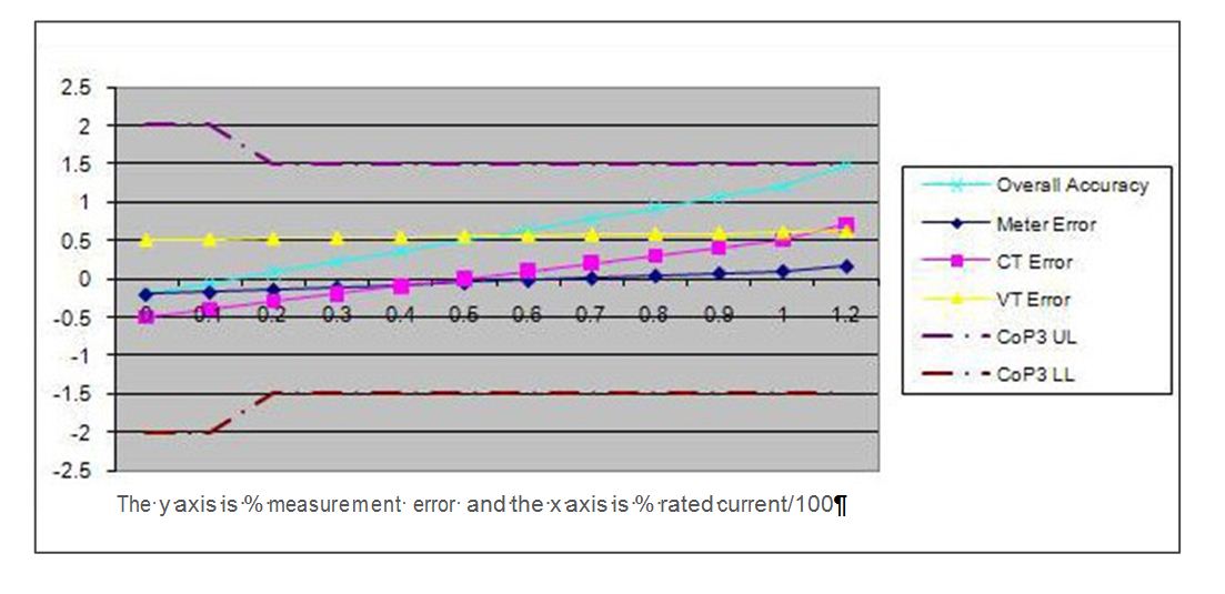
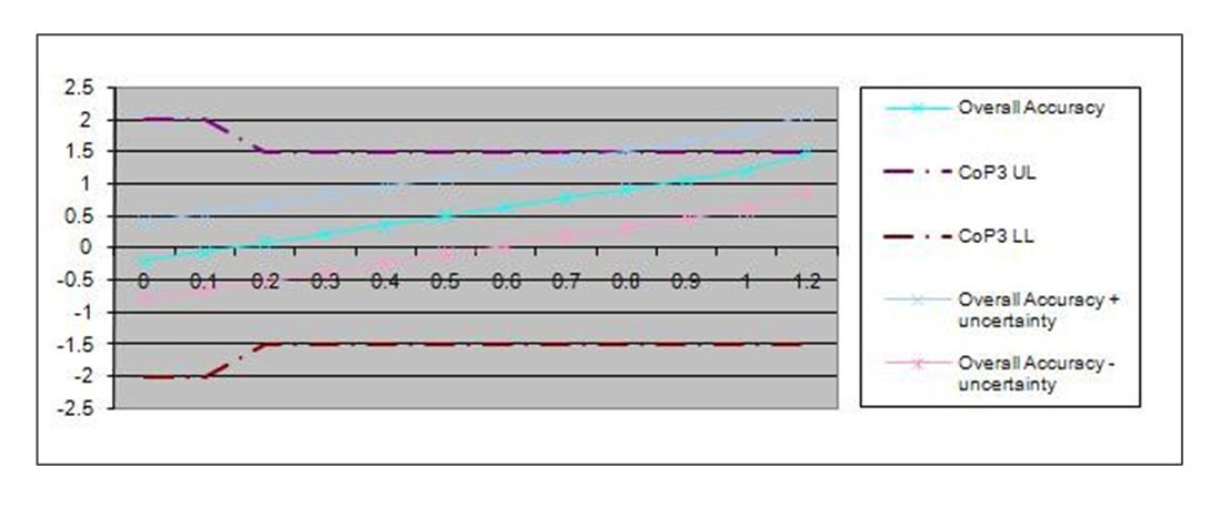
    • Replace an item or items of Metering Equipment with a better (higher) accuracy class; or

    • Calibrate an item or items using Calibration equipment with a better (lower value) measurement uncertainty statement; or

    • Compensate the Meter to bring the Overall Accuracy curves within the UL and LL of CoP3.

What happens when Compensation is applied to a Meter?

Taking the third option, Compensation of -0.8 is added to the Meter over the entire current range resulting in the following overall accuracy curve (with measurement uncertainty shown):

complex image of process

We can now be much more confident that the actual Overall Accuracy of the Metering System will be within the limits of measurement error set out in CoP3.

Bear in mind that the measurement errors obtained during Calibration are obtained under reference conditions, therefore think about the factors that could influence the figures for overall accuracy on site (e.g. the ambient temperature at the Metering Equipment location).

For CoP1 and 2 Metering Systems you may not be able to achieve the Overall Accuracy using the method above. In this case, you’ll need to do a Compensation calculation to achieve a suitable Compensation for the Meter. Consider including the following factors:

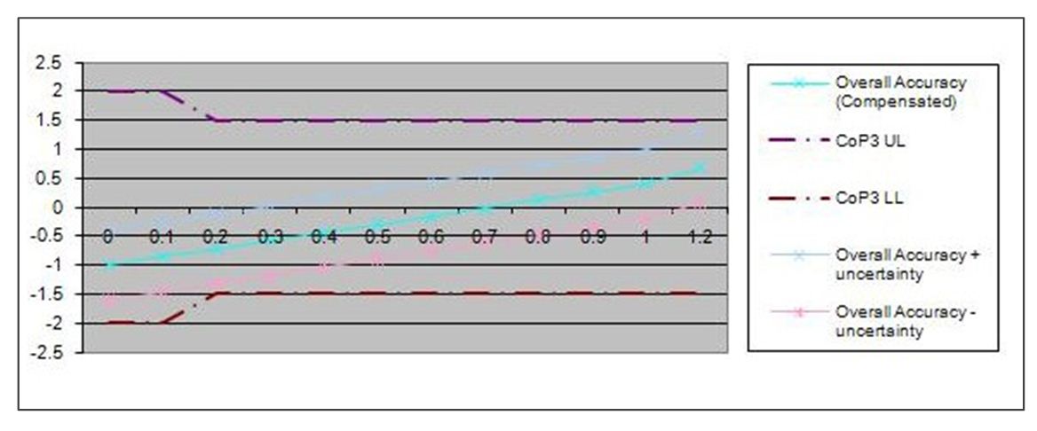
    • CT error at actual burden (which may change with loading);

    • VT error at actual burden (which may change with loading);

    • Any influences due to non-Settlement burdens (and any changes to these burdens);

    • Voltage drop in leads (and associated circuitry) connecting measurement transformers; and

    • Power transformer iron and copper losses (which vary with loading).

You’ll need to appoint someone with the right skills set to carry out Compensation calculations as they are very complex and accuracy is absolutely vital.

Need more information?

Useful links:

If you would like more guidance on this topic, or if you have any questions about CoP4 or metering in general, please contact metering@elexon.co.uk.

For further information please contact the BSC Service Desk or call 0370 010 6950.

Intellectual Property Rights, Copyright and Disclaimer

The copyright and other intellectual property rights in this document are vested in Elexon or appear with the consent of the copyright owner. These materials are made available for you for the purposes of your participation in the electricity industry. If you have an interest in the electricity industry, you may view, download, copy, distribute, modify, transmit, publish, sell or create derivative works (in whatever format) from this document or in other cases use for personal academic or other non-commercial purposes. All copyright and other proprietary notices contained in the document must be retained on any copy you make.

All other rights of the copyright owner not expressly dealt with above are reserved.

No representation, warranty or guarantee is made that the information in this document is accurate or complete. While care is taken in the collection and provision of this information, Elexon Limited shall not be liable for any errors, omissions, misstatements or mistakes in any information or damages resulting from the use of this information or action taken in reliance on it.

1 Where the measurement transformers are not at the Defined Metering Point then a Metering Dispensation is required (see BSCP32: Metering Dispensations).

2 Where no Communications Equipment is fitted the Data Collector will take Meter readings locally, using a hand held unit.

3 Guidance on testing single phase voltage transformers will be added as it becomes available.

4 Primary source should be a direct source where possible using a current clamp ammeter and voltmeter. You could use an independent current transformer which has its primary connection in series with the metering current transformer or independent energy meters, voltage and current meters.

5 The Compensation applied should reflect the electrical losses between the DMP and the AMP. In some cases, the difference may be negligible but the Compensation will still be the subject of a Metering Dispensation.

6 Under CoP4, measurement uncertainty needs to be determined to a confidence level of 95% or greater. Assuming a normal Gaussian distribution applies, then a coverage factor (k) of 2 will give a 95.45% confidence level (or coverage probability). Read the UKAS document, M3003 ‘The Expression of Uncertainty and Confidence in Measurement’ for more information.

7 Modern static Meters present low burdens to measurement transformers and so you should consider whether the operating burden on the measurement transformers are within their operating ranges. In such cases it may be necessary to add additional burden and as a consequence the individual error contributions may change.