Generic LED Charge Codes: Guidance to Manufacturers on the Application Process |
Guidance Note |
Why has this guidance been provided?
A majority of the Charge Code applications that Elexon receive are for Light Emitting Diode (LED) Lighting. Since the introduction of Generic LED Charge Code Ranges in July 2016, there have been numerous queries received by Elexon regarding how the new Generic LED Charge Codes work and what Elexon requires from a manufacturer to process a Charge Code request.
This document details and defines the structure of Generic LED Charge
Code Ranges and explains the documents Elexon require from a manufacturer for a Generic LED Charge
Code Range to be issued. This document also provides an overview of the application process and key steps involved in each application cycle and why Charge
Codes can take weeks to be approved. Further detail can be found in the
UMS Operational Information Document (OID).
What are Generic LED Charge Code Ranges?
Generic LED Charge Code Ranges are a requirement for LED lighting equipment to be connected to the Distribution Network via an Unmetered Supply. Charge Codes are used by customers to identify unmetered equipment in their inventory. The circuit watts associated with the Charge Code will be used in the consumption calculation.
The difference between Generic LED Charge Code Ranges and standard Charge Codes (traffic and miscellaneous equipment and legacy LED Charge Codes) is the use of a ‘lower and upper limit’. Due to the capability of LED Lighting equipment to be set to different light output levels, a range of potential Charge Codes is provided that reflects the maximum and minimum power levels of manufacturers’ products.
Prior to the Generic LED Charge Code Ranges, there used to be a unique Charge Code created for each power level of a piece of lighting equipment. With the new Generic LED Charge Code Ranges, all wattages between the minimum and maximum power levels are available within the same Charge Code Range, and no longer need numerous Charge Codes to be approved for different power levels.
The Structure of Generic LED Lighting Charge Codes
Generic LED Charge Codes Ranges are for LED Lighting, i.e. Street Lights, Illuminated Signs, aesthetic lighting or other purposes, but not for traffic signals.
Digits | Description |
1 and 2 | Always 42 |
3, 4, 5 and 6 | The Circuit Watts of the equipment in watts, i.e. ‘0250’ represents a lamp with a power rating of 250 watts. For lamps with driver enabled Constant Light Output (CLO) this will be the mid-life value. See note below for Central Management System (CMS) controlled CLO. |
7, 8, 9 and 10 | Always 0000 if Circuit Watts is over 1. If Circuit Watt is less than 1 Watt then digit 10 will denote the decimal rating. |
11, 12 and 13 | Always 100 |
Definition of digits 1 and 2:
The value of 42 defines the product as LED lighting.
Definition of digits 3, 4, 5 and 6
These represent the Circuit Watts of the equipment in Watts (W) at full power, i.e. ‘0250’ represents a lamp with a full power rating of 250 watts. For lamps with
driver enabled CLO this will be the mid-life value. For Equipment that is less than 1 Watt, digits 3, 4, 5 and 6 will be rendered to ‘0000’.
Definition of digits 7, 8, 9 and 10
For other lighting these digits can be used to define the manufacturer or type of driver or ballast, for these generic codes it will always be 0000. For Equipment that is less than 1 Watt, BSCCo will issue circuit watts to the nearest one decimal place, e.g. 0.45 = 0.5 Watts (1.d.p.), making use of the ‘set’ of digits 7, 8, 9 and 10. Specifically, digit 10 will denote the decimal rating.
Definition of digits 11, 12 and 13
The value of 100 defines that these Charge Codes are the full power rating for the lamp.
Where the Circuit watts is over 1 Watt, for example circuit watts is measured at 250 Watts, the Charge Code entered on the inventory would be 4202500000100.
Where the circuit watt is under 1 Watt, for example circuit watt is measured at 0.9 Watt, the Charge Code entered on the inventory would be 4200000009100.
What is the difference between ‘Reduced Operation’ and Dimming?
Reduced Operation refers to LED equipment where the usual operation of the equipment at full power is less than the maximum power of the LED driver capability. For example, a manufacturer’s product line may consist of multiple versions of the same LED and LED driver combination, but pre-set to a variety of Reduced Operation levels, such as 100 Watts, 80 Watts and 60 Watts for normal dusk to dawn operation at a constant level.
Dimming refers to the reduction of light output and power input of LED equipment to less than either the full power or Reduced Operation level during part of the dusk to dawn operation. The reduction in power consumption from part night dimming is calculated by linking the full power (or Reduced Operation) Charge
Code with alpha-numeric Variable Power Switch Regimes that are published on the
Variable Power Switch Regime Spreadsheet. For example, a luminaire may switch on at 100 Watts and during the night be ‘dimmed’ to 50% of full power (i.e. 50 Watts). Dimming is not a consideration in the application for Generic LED Charge
Code Ranges. Dimming of Generic LED Charge
Codes and other lighting equipment Charge
Codes (ending with 100) is accommodated by linking the Charge
Code with one of the alpha- numeric Variable Power Switch Regimes are published in the
Variable Power Switch Regime Spreadsheet.
Note: dimming controlled by a Central Management
System (CMS) does not require a Variable Power Switch Regime instances of dimming is reported through the CMS event log provided to the
Meter Administrator.
How are Lower and Upper Product Limits determined?
Every Generic LED Lighting Charge Code Range comes with a ‘lower limit’ and ‘upper limit’. If a manufacturer has a product range that uses the same LED driver then an application for the whole range of products can be made. This would be the Elexon preferred option as it limits proliferation of LED charge Code ranges. However, manufacturers may wish to differentiate products by the number of LEDs in the product/ driver combination. Products that are electronically identical but have differences in physical appearance should not require separate ranges.
In making the application, the manufacturer should determine the lower limit of the range by identifying the lowest wattage level of Reduced Operation. The upper limit should be the wattage of the product at its highest power level, which could be the driver at full power or the product at its highest Reduced Operation level.
For example, a Generic LED Charge Code Range that has products ranging from 100 Watts (which is either the maximum allowable driver input or the highest reduced operation level), to 20 Watts (which may be the lowest Reduced Operation version sold to customers), would have a lower and upper limit as follows:
Lower Limit | Upper Limit |
4200200000100 | 4201000000100 |
If a piece of lighting equipment runs at a constant power level (for example an LED sign, or a product that does not have any Reduced Operation variants) then the lower limit and upper limit will be the same value.
How do manufacturers apply for the Generic LED Charge Codes?
In order to apply for Generic LED Charge Codes Ranges, you must provide the following documents:
A completed application form
Test Data obtained from an ISO 17025 accredited test house along with a clear description of the equipment (including the Product Name and Product Code, and version number if applicable, used by the manufacturer), its typical operation and installation. Specific details on testing requirements can be found on the next page.
A certificate of the ISO 17025 accredited test house. Test houses that have ISO 17065 can apply to Elexon to provide a service to third parties that are not ISO 17025 accredited. The accredited test house must ensure the third party can meet the appropriate testing standards and must review and issue test reports on behalf of the third party;
A brochure or product specification of the equipment and pictures.
What are the testing requirements for LED lighting equipment?
The purpose of the testing procedure is to provide an accurate indication of the load at the Distribution Network terminals of the particular equipment under normal conditions; i.e. to establish what consumption would be recorded by a standard meter fitted at the supply terminals.
When conducting testing, the circuit watts and Volt Ampere (VA) should be measured at five different voltage levels from 210V, increasing in 10V increments up to 250V (at 50Hz). A sample size of five is required unless, on review of the test data, it is determined that more samples are needed. For example:
Manufacturer’s name and equipment model name: …………………………………..
Voltage | | Sample 1 | Sample 2 | Sample 3 | Sample 4 | Sample 5 |
210 | Watts | | | | | |
VA | | | | | |
220 | Watts | | | | | |
VA | | | | | |
230 | Watts | | | | | |
VA | | | | | |
240 | Watts | | | | | |
VA | | | | | |
250 | Watts | | | | | |
VA | | | | | |
For LED lighting equipment, the five samples at 210-250V will be tested at the equipment’s full power level (which may be Reduced Operation or full driver power).
For LED lighting equipment with different product ranges the above testing procedure must be conducted at five different power levels (including full power). The five points of test data must include the driver at full power, at the lowest Reduced Operation power level and then at three other separate equally spaced power levels in between. For example, if a product runs at 100W when at full power, and runs at a Reduced Operation power level of 20W, we require test data at those two points, and also three points in between those values, i.e. at 80W, 60W and 40W.
The five different power level measurements are required to ensure consistency in the equipment’s dimming capabilities. This allows us to extrapolate intermediate power levels. We still expect the test data to include both Watts (W) and Volt-Amps (VA). However, we shall not consider or reject applications based on the derived power factors since we are assuming a unity power factor.
When submitting an application, you must clarify what the test data represents. This includes stating any and all Reduced Operation variants.
Generic LED Charge Code Ranges will only be created based on the test data provided. If the data provided is not clear, the application may be rejected, or a customer may refuse to connect the equipment to an Unmetered Supply due to a lack of proof of consumption below the lower limit.
Manufacturer | Manufacturer's Designation | Generic LED Codes – Lower Limit | Generic LED Codes – Upper Limit |
Philips Lighting | 40W Xitanium Driver | 4200080000100 | 4200400000100 |
Holophane Europe Limited | DSX2 100 LED | 4201460000100 | 4202320000100 |
Urbis Schréder | 8 LED LF | 4200100000100 | 4200190000100 |
Once published, you must inform customers of the appropriate Charge Codes for the equipment they have purchased. Ideally, we would expect Manufacturers to label the Apparatus with the appropriate Charge Code that matches the configuration.
What about Constant Light Output (CLO)?
Applications for CLO Generic LED Charge Codes should include evidence of the beginning, mid, and end-of-life in any test data. This data shall be provided for all equipment that has driver enabled CLO functionality. For this purpose mid-life is halfway through the design life of the product.
E.g. If the end-of-life current is 20% higher than the beginning-of-life current, then the driver output current should be adjusted to simulate ‘end of life’ conditions and the appropriate measurements taken.
This may be achieved by using a resistor or other methodology. A clear statement of the methodology employed shall be supplied with the application. The mid-point of the beginning of ‘life’ and ‘’end of life’ circuit watts will be used by BSCCo to define the Charge Code.
Applying for CLO Generic LED ranges
When applying for a Generic LED Charge Code range the manufacturer needs to consider the mid-life Circuit Watts of the CLO product at both the bottom and top of the range applied for. For example, if a product without CLO has a power level of 50W at the bottom of the range, the CLO version may have a start of life at 45W and an end of life power level of 53W, the mid-point would be 49W which reflects the saving made from CLO.
When informing customers of the Generic LED Charge Code, manufacturers must declare the 42 Series Generic LED Charge Code that has the Circuit Watt value (digits 3 to 6) that matches the approved ‘mid-life’ value. For example, if the mid-life value for an LED street light is 49W then the manufacturer should declare the Generic LED Charge Code as 4200490000100.
Note: that CLO & dimming controlled by a Central Management System (CMS) does not need a CLO Charge Code or Variable Power Switch Regime as the variation in power levels to facilitate CLO and any dimming is reported by the CMS event log output.
What is the approval process for Charge Codes?
Unmetered Supplies Charge Codes and Switch Regimes are released as part of the monthly Market Domain Database (MDD) publishes. MDD contains Electricity Market information and is essential to the operation of the Supplier Volume Allocation (SVA) trading arrangements. Because Charge Codes and Switch Regimes are used by Unmetered Supply Operators (UMSOs) and Meter Administrators (MAs) to calculate the consumption of unmetered equipment, it is essential that Charge Code applications are fully scrutinized and assessed by a variety of industry bodies before they can become valid for use in Settlements.
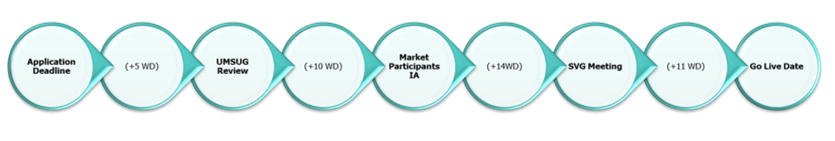
A full Charge Code application can take approximately two months from the date of the application cycle deadline, to the date in which the Charge Code becomes valid for use in Settlements through an MDD publish. In between those dates, there are various approval bodies that review Charge Code applications, and manufacturers may be contacted during these reviews and asked to provide further information on their lighting equipment, or explain any inconsistencies in provided test data.
In the five working days between the application deadline and UMSUG (Unmetered Supply User Group) review, Elexon create ‘proposed’ charge codes based on the test data provided by the manufacturer and calculate an average circuit watt using an average of the samples provided.
The Unmetered Supply User Group (UMSUG) is a committee consisting of various industry members related to Unmetered Supplies, including members from Elexon, Meter Administrators, Unmetered Supply Operators and technical experts in areas such as lighting and traffic equipment. During the UMSUG review, UMSUG members assess the proposed Charge Codes created by Elexon and may propose amendments or rejections, or have queries to pass on to the manufacturers.
After the UMSUG review is the Market Participants Impact Assessment (MPIA). This is where the Charge Codes begin to tie into the MDD release cycle. As Charge Codes are processed as part of MDD, all applications are assigned a ‘Change Request’ number for that particular MDD cycle, and must be assessed by all Market Participants like every other Change Request for that cycle. Market Participants are Parties that are signed up to the BSC. Because there are various non-UMS related Change Requests being assessed, the impact assessment lasts for 14 working days.
The next stage is the Supplier Volume Allocation Group (SVG) Meeting. This is where all Change Requests for an MDD cycle (including the UMS Change Request) are officially approved for use in Settlements by a committee consisting of various industry members.
In the 11 working days after the SVG Meeting, all approved Change Requests are ‘published’ into the live MDD database and industry flows are sent out to all Parties that include the new changes to the database. To allow time to rectify any potential errors with the flows or data, there is an 11 day period before all approved Change Requests ‘go live’. During this time, the live Charge Code spreadsheets on the Elexon website are updated with approved Charge Codes, but are not valid for use in Settlements until the agreed go live date for all Change Requests of that MDD cycle. During this period, manufacturers may request to see if their Charge Code application was approved and find out in advance what their Charge Code is.
Where can I get more information?
Intellectual Property Rights, Copyright and Disclaimer The copyright and other intellectual property rights in this document are vested in Elexon or appear with the consent of the copyright owner. These materials are made available for you for the purposes of your participation in the electricity industry. If you have an interest in the electricity industry, you may view, download, copy, distribute, modify, transmit, publish, sell or create derivative works (in whatever format) from this document or in other cases use for personal academic or other non-commercial purposes. All copyright and other proprietary notices contained in the document must be retained on any copy you make. All other rights of the copyright owner not expressly dealt with above are reserved. No representation, warranty or guarantee is made that the information in this document is accurate or complete. While care is taken in the collection and provision of this information, Elexon Limited shall not be liable for any errors, omissions, misstatements or mistakes in any information or damages resulting from the use of this information or action taken in reliance on it. |