Asset Metering |
Guidance Note |
|
This guidance note relates to the Settlement of Secondary BM Units (BMU) using metering behind the site Boundary Point. Metering behind the site Boundary Point used for this purpose is referred to as Asset Metering and is compliant with Section L of the Balancing and Settlement Code (BSC) and Code of Practice (CoP) Eleven.
An Asset Metering System will be assigned an Asset Metering System ID (AMSID) for Active Energy Import and, if applicable, Active Energy Export. The Asset Metering Virtual Lead Party (AMVLP) can assign AMSIDs within the same Grid Supply Point (GSP) area into a Secondary BMU. Asset Metering Systems must be installed behind a Half Hourly Boundary Point Metering System.
Asset Metering Systems can only be Registered by an AMVLP who has qualified in that role. The AMVLP is responsible for appointing qualified Asset Metering Party Agents to manage the Meter Operations and Data Collection for Asset Metering Systems.
Asset Metering Systems can only be Registered by a Supplier for the purposes of submitting an EMR AMSID declaration. A Supplier cannot use an Asset Metering System in a Secondary BMU.
Supplier Volume Allocation (SVA) Meter Operator Agent (MOA) or an Asset Metering Meter Operator Agent (AMMOA);
Half Hourly Data Collector (HHDC);
Asset Metering Half Hourly Data Collector (AMHHDC) (if applicable).
This document is relevant to AMVLPs, Suppliers and Asset Metering Party Agents and covers:
Asset Metering;
Asset Metering Types;
Asset Meters
Measurement transformers;
Commissioning and Proving;
Compliance and Protocol approvals;
Meter Technical Details; and
Data submission and transfer
Registration of Assets, Asset Metering Party Agents and Asset Meters; and
Asset Differencing and Complex Sites.
An Asset consists of Plant and Apparatus that is controllable and can be despatched on request to deliver a Balancing Service. These Dispatchable Assets can be a source of generation or a demand that can be switched on, or off, or modulated as required.
All of the Asset’s Dependent Load must be metered using one or more Half Hourly Asset Metering Systems. A Dependent Load is any source of demand, or generation that is directly associated with the Dispatchable Asset. This includes the output of the Asset itself and any circuit that will change its mode of operation or level of output in direct response to the Dispatchable Asset being activated. For a Generating Unit Dependent Load must include all Auxiliary Load for that Generating Unit and the generated output.
Where an Auxiliary Load means the total amount of electricity used by a Generating Unit for purposes directly related to its operation, whether or not that electricity is generated by the unit or used while the unit is generating electricity.
Alternatively, an AMVLP may meter the Independent Load and use a differencing arrangement. Where the Independent Load is any source of demand, or generation that is not directly associated with the Dispatchable Asset but is located behind the same Boundary Point Metering System. This includes any circuit that will not change its mode of operation or level of output in direct response to the Dispatchable Asset being despatched.
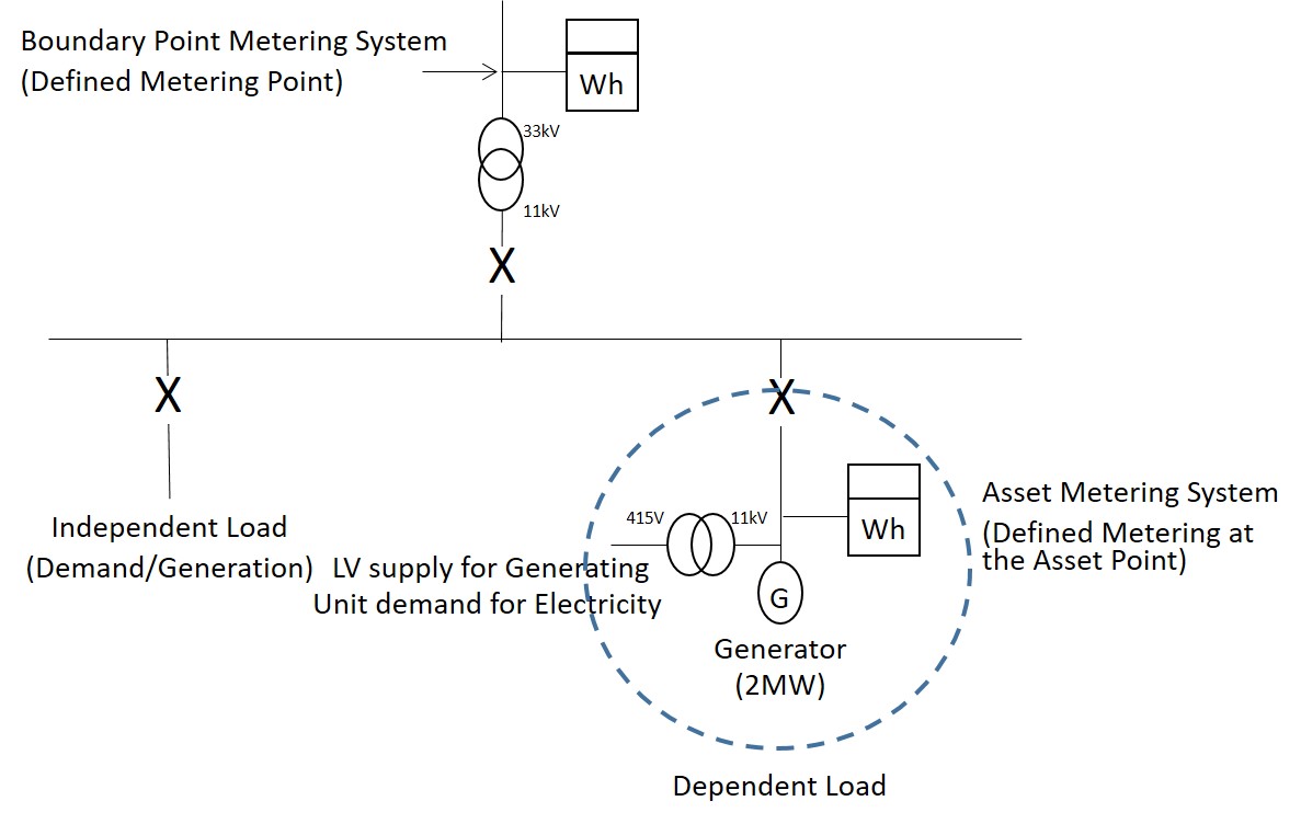
The following examples go through metering configurations of the typical variations. The Actual Metering at the Asset Point should be in such a position to measure all the Dependent Load related to the Asset. This can be achieved through multiple Asset Metering Systems or by using Asset Differencing. For a Generating Unit, the Net Output can be measured by one or more Asset Metering Systems.
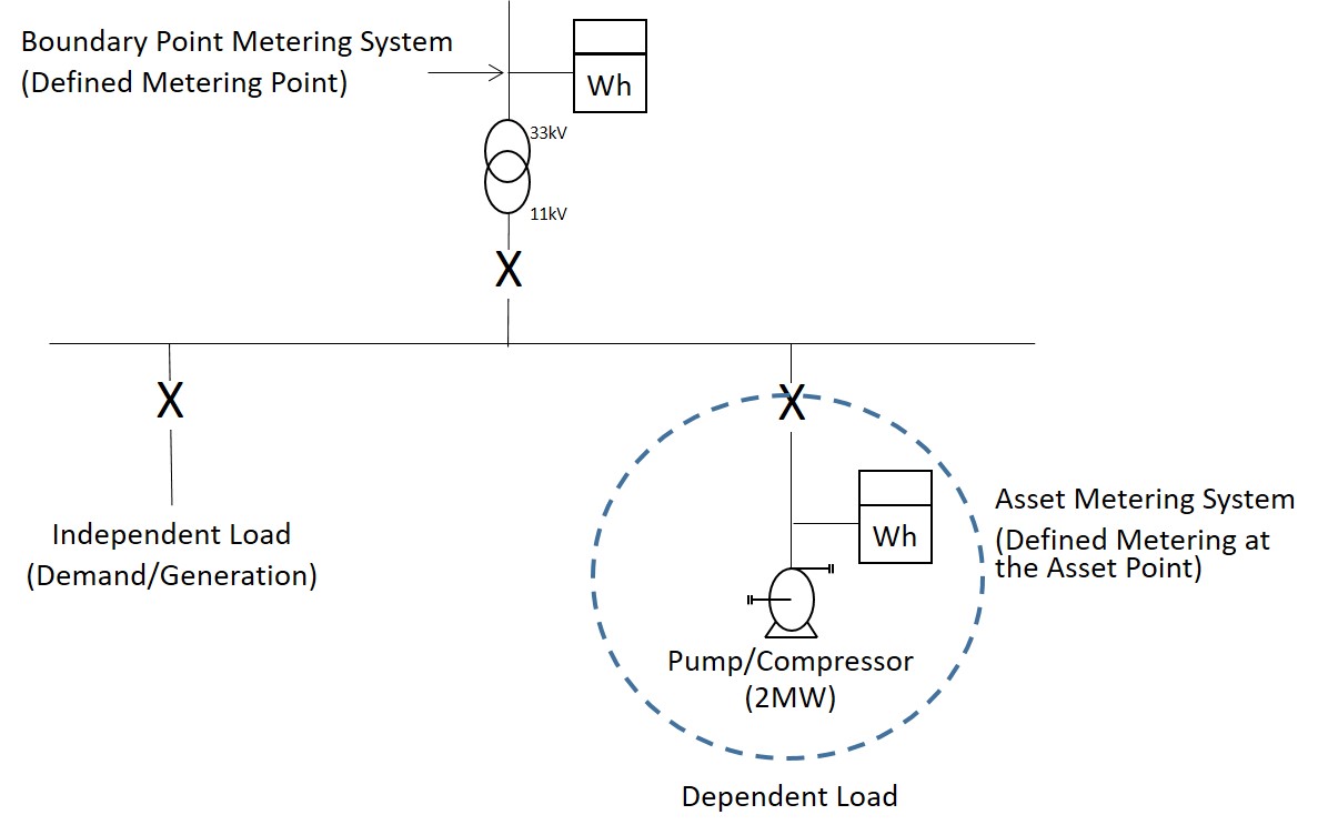
Figures 1 and 2 respectively show the required location of the measurement transformers of an Asset Metering System for a Dispatchable Generation Unit Asset and a Dispatchable Load demand Asset.
Figure 1: Asset Metering System physical location (Generating Unit Asset)
Figure 2: Asset Metering System physical location (demand Asset)
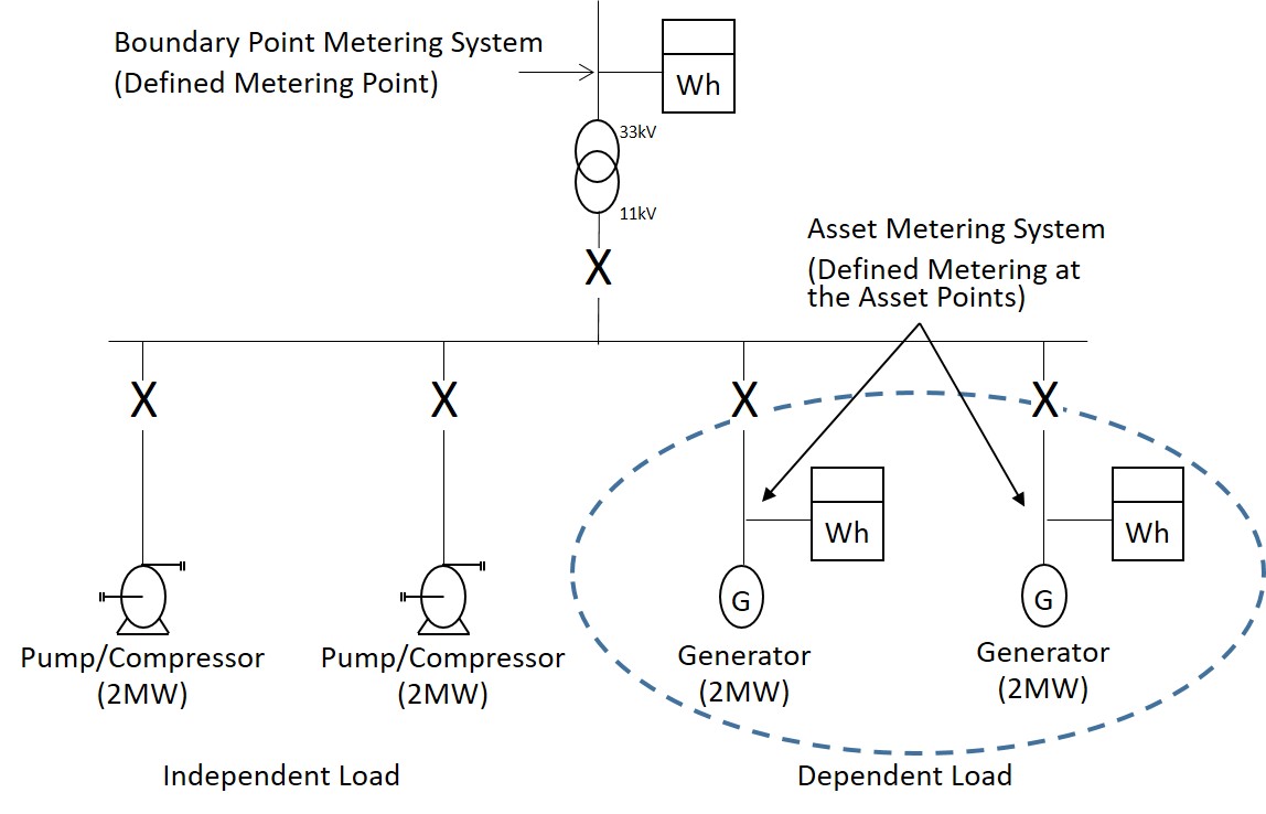
Figure 3 shows the use of multiple Asset Metering Systems to measure all the Dependent Load. In the example there are two Dependent Load circuits that must be metered and they will make up the Asset Metering System for the Asset.
Figure 3: Multiple Asset Metering Systems physical location (demand Asset)
In Asset Metering the technical requirements for the Metering Equipment are split into categories called Asset Metering Types and are split by, either the rated capacity of the circuit being measured or by the Maximum Demand of the energy transfers of the circuit being measured. There are five categories:
1. Asset Metering Type 1 - Metering of circuits with a rated capacity greater than 100MVA;
2. Asset Metering Type 2 - Metering of circuits with a rated capacity not exceeding 100MVA;
3. Asset Metering Type 3 - Metering of circuits with a rated capacity not exceeding 10MVA;
4. Asset Metering Type 4 - Metering of energy transfers with a Maximum Demand of up to (and including) 1MW; and
5. Asset Metering Type 5 - Metering (embedded within another device) for energy transfers with a Maximum Demand of up to (and including) 100kW.
The requirements for Metering Equipment are different for each category and to be compliant the equipment installed must meet the requirements for Asset Meters and measurement transformers specified for the relevant Asset Metering Type.
Each Asset Metering Type has a specified limit of overall accuracy that, when assessed, must include all items of Metering Equipment making up that Asset Metering System i.e. inclusive of Asset Meters and measurement transformers.
All Asset Metering Systems must provide metered data in 30-minute Settlement Period format; this can be either recorded directly in the Asset Meter or converted to the correct format by a software solution that must be based on the output from an Asset Meter. The National Electricity Transmission System Operator (NETSO) requires data that is more granular and aggregated up to Secondary BMU level. The AMVLP must provide this data to the NETSO, the technical requirements for operational metering are not in scope of Code of Practice 11 and detailed in the appendices of the Virtual Lead Party Agreement (VLPA). The requirements for provision of balancing services to NETSO will be additional to these operational and settlement metering requirements and will be detailed as part of the balancing services contract.
Asset Meters are devices for measuring Active Power and/or Active Energy. All Asset Meters must have had an initial calibration to demonstrate compliance to the relevant standard or, in the case of Asset Meters for Asset Metering Type 5, the requirements specified in Code of Practice 11. Calibration certificates must be produced using verifiable standards and indicate conformity with the accuracy requirements appropriate to the Asset Meter’s relevant accuracy class.
Asset Meters do not need to be replaced so long as the Asset Meter continues to meet the stipulated accuracy requirements, however the Asset Meter must be re-calibrated every:
For Asset Metering Type 4 (whole current) and Asset Metering Type 5 the Asset Meter or Embedded Metering Device shall be designed by the manufacturer to remain accurate for the life expectancy of the Asset Meter or equipment containing the Embedded Metering Device.
Calibration certificates must be retained for the lifetime of the Asset Metering System.
Evidence of continued compliance of an
Asset Meter or Embedded
Metering Device to the relevant standard or accuracy limits specified in
Code of Practice 11
shall be made available for inspection. This evidence can be from calibration tests on an
Asset Meter or equipment containing an Embedded
Metering Device on a device removed from site where it was no longer required, but where no device(s) are available, the AMVLP or
Supplier will be required to remove the device(s) from site for test or arrange to test them at site. The
BSC Panel shall determine the number of
Asset Meters or Embedded
Metering Devices required to be tested to confirm continued compliance with the allowed limits of error for the relevant accuracy.
Asset Meters cannot be used as Active Energy Meters provided for the metering of supplies to customers unless they shall be in accordance with Schedule 7 of the Electricity Act 1989 and approved under the Measuring Instruments Directive / Measuring Instruments Regulations.
Where an Asset Meter is intended to be used for a purpose, other than solely for the Settlement of Secondary BMUs, it can be used for other purposes as long as the requirements of Code of Practice 11 are met. Where the other intended purpose has additional requirements over and above that in Code of Practice 11 it is up to the manufacturer of the Asset Meter, or the end user, to confirm that the Asset Meter is compliant with the relevant governing documents for other schemes. Compliance testing under the BSC will only confirm compliance with the relevant Asset Metering Type in Code of Practice 11.
Asset Meters have been split into three categories each with a mandatory minimum accuracy class. You can choose to exceed these requirements to install a more robust and accurate Asset Meter, for example, by installing an Asset Meter of a better accuracy class than the specified minimum.
1. An Asset Meter approved for use in Code of Practice 1, 2, 3, 5 and 10 that is a Half Hourly Integral Outstation Meter;
The Meter has already been approved for Settlement purposes and is automatically approved for use in the equivalent Asset Metering Type (see table 1) and as such does not require any additional Compliance Testing under BSCP601.
Table 1: Asset Metering Type / Code of Practice equivalence
Asset Metering | | Settlement (HH) |
Asset Metering Type 1 | Code of Practice 1 |
Asset Metering Type 2 | Code of Practice 2 |
Asset Metering Type 3 | Code of Practice 3 |
Asset Metering Type 4 | Any | Code of Practice 5 |
< 100kW only | Code of Practice 10 |
They must also meet the required accuracy class specified in table 2 for the relevant Asset Metering Type.
Table 2: Required accuracy classes for Asset Meters – Category 1
Asset Metering Type | Accuracy Class |
1 | All | 0.2S |
2 | All | 0.5S / C |
3 | All | 1 / B |
4 | Transformer Connected | 1 / B |
Whole Current | 2 / A |
It is good industry practice to install a main and check Asset Meter for Asset Metering Types 1, 2 and 3 to mitigate the risk of failure of an Asset Meter preventing data being submitted to Settlement.
1. An Asset Meter whose primary purpose is the measurement of Active Power and/or Active Energy that is not an approved4 Half Hourly Integral Outstation Meter;
This category of Asset Meter includes any Meter that has not already been approved for Settlement purposes. All Meters in this category require to complete Compliance Testing for an Asset Meter under BSCP601. Where an Asset Meter has completed Compliance Testing it is only for the relevant Asset Metering Type and it is not approved for use in the equivalent Code of Practice. Should an applicant wish to use the Meter in Half Hourly Settlement the Meter would have to complete Compliance Testing against the relevant Code of Practice (i.e. CoP 1, 2, 3, 5 and 10 as applicable).
All Asset Meters in this category must be manufactured to and shall be compliant with a recognised national or international standard such as International Electrotechnical Commission (IEC); European Committee for Electrotechnical Standardization (CENELEC); International Organization for Standardization (ISO); British Standards Institution (BSI). They must also meet the required accuracy class specified in table 3 for the relevant Asset Metering Type.
Table 3: Required accuracy classes for Asset Meters – Category 2
Asset Metering Type | Accuracy Class |
1 | All | 0.2S / 0.2 |
2 | All | 0.5S / 0.5 / C |
3 | All | 1 / B |
4 | Transformer Connected | 1 / B |
Whole Current | 2 / A |
It is good industry practice to install a main and check Asset Meter for Asset Metering Types 1, 2 and 3 to mitigate the risk of failure of an Asset Meter preventing data being submitted to Settlement.
1. An Asset Meter whose primary purpose is not the measurement of Active Power and/or Active Energy and is not a Half Hourly Integral Outstation Meter. These Embedded Metering Devices are embedded within equipment used for purposes other than the measurement of Active Power and/or Active Energy, such as an EV charging unit or a small scale domestic battery storage unit.
An Embedded Metering Device is an Asset Meter, measuring Active Power and/or Active Energy that is embedded within equipment used for other purposes (e.g. an EV charging unit or a small scale domestic battery storage unit) and is not a dedicated meter, i.e. one whose primary purpose is to measure Active Power and/or Active Energy.
Where the equipment is converting a.c. electrical quantities to d.c. electrical quantities, or converting d.c. electrical quantities to a.c. electrical quantities, the Embedded Metering Device shall be in such a place within the equipment to account for any losses associated with the inverter or rectifier (i.e. is located on the a.c. side of the inverter or rectifier). Where it is not, the losses of the inverter and/or rectifier must be accounted for in the aggregation rule using the Asset Metering Complex Site Supplementary Information Form (CoP11/Fa) (see section on Asset Differencing and Complex Sites). The losses in the inverter and/or rectifier must be independently verified (in accordance with BSCP601 ‘Metering Protocol Approval and Compliance Testing’ for Code of Practice 11) and results made available for inspection by the Panel or Technical Assurance Agent.
The inverter or rectifier loss tests, where applicable, should be for a specific make, model and type and where the inverter or rectifier make, model and type is changed the inverter or rectifier loss tests should be carried out again, as described above. Where the losses have changed the new figure must be used in the Asset Metering Complex Site Supplementary Information Form (CoP11/Fa) for the relevant configuration of device.
All Meters in this category require to complete Compliance Testing for an Asset Meter under BSCP601.
They can only be used for Asset Metering Type 5 which is limited to less than 100kW and they must meet the required accuracy class specified in table 4 for a.c. Asset Meters and table 5 for d.c. Asset Meters.
Table 4: Required accuracy classes for a.c. Asset Meters – Category 3
Condition | Limits of Error at stated system Power Factor |
Frequency range | Voltage expressed as the operational range of the device | Current expressed as the operational range of the device | Power Factor | Limits of Error |
From 49.0 Hz to 51.0 Hz | 90% to 110% Un inclusivea | 50% Imax to Imax inclusive | 1 | ± 2.0% |
In to 50% Imax | 1 | ± 2.5% |
In to Imax inclusive | 0.5 lag and 0.8 lead | ± 2.5% |
a. Where Un is one of the nominal voltage values for a.c. meters specified in BS EN/IEC 62052-11 section 4.1.1 Table 1 |
Table 5: Required accuracy classes for d.c. Asset Meters – Category 3
Condition | Limits of Error at stated system Power Factor |
Voltage expressed as the operational range of the device | Current expressed as the operational range of the device | Power Factor | Limits of Error |
90% to 110% Un inclusivea | 50% Imax to Imax inclusive | N/A | ± 2.0% |
In to 50% Imax | N/A | ± 2.5% |
a. Where Un is one of the nominal voltage values for d.c. meters specified in BS EN/IEC 62052-11 section 4.1.1 Table 1 |
Where In is the nominal current the device is designed to operate at (i.e. the lowest value of current that will meet the accuracy requirements as specified by the manufacturer) and Imax is the maximum current the device is designed to operate at. For example, if a device was designed to only operate in the 6A-32A range In would be 6A and Imax would be 32A.
Where an Asset Metering System requires to step down current and voltage to the Asset Meter measurement transformers shall be used that must be of a wound construction and compliant with IEC standard BS EN/IEC 61869-2, 61869-3 and 61869-4 as applicable.
All measurement transformers must have had an initial calibration to demonstrate compliance to the relevant standard. Calibration certificates must be produced using verifiable standards and indicate conformity with the accuracy requirements appropriate to the measurement transformers relevant accuracy class.
Calibration certificates must be retained for the lifetime of the Asset Metering System
The minimum required accuracy classes for measurement transformers and the configuration are dependent on the Asset Metering Type, see table 6 for Current Transformers (CT) and table 7 for Voltage Transformers (VT): You can choose to exceed these requirements to install a more robust and accurate Asset Metering System, for example, by installing a CT or VT of a better accuracy class than the specified minimum.
Table 6: Required accuracy classes and configuration for Current Transformers
Asset Metering Type | Minimum Accuracy Class | No. of CTs Required | Configuration Requirements |
1 | 0.2S | 2 | 1 Set of CTs shall be dedicated to the main Asset Meter only and 1 set supplying the check Asset Meter. Check Asset Meter CTs can be used for other purposes providing the CoP accuracy requirements are met. |
2 | 0.2S | 1 | CTs shall be dedicated to Settlement purposes supplying both main Asset Meter and check Asset Meter. An additional set of CTs may be fitted for the check Asset Meter which may also be used for other purposes providing the CoP accuracy requirements are met. |
3 | 0.5 | 1 | 1 set of CTs for main Asset Meter and check Asset Meter for Settlement purposes, but can be used for other purposes if the CoP accuracy requirements are met. |
4 | 0.5 | 1 | 1 set of CT for the main Asset Meter for Settlement purposes, but the CTs may be used for other purposes provided the CoP accuracy requirements are met. |
Table 7: Required accuracy classes and configuration for Current Transformers
Asset Metering Type | Minimum Accuracy Class | No. of VTs Required | Configuration Requirements |
1 | 0.2 | 2 VTs (or 1 VT with two (2) or more secondary windings) | 1 VT secondary winding dedicated to the main Asset Meter for Settlement purposes only. A second VT secondary winding for the check Asset Meter, which may also be used for other purposes providing the CoP accuracy requirements are met. |
2 | 0.5 | 1 | VT secondary winding shall be dedicated to Settlement purposes supplying both main Asset Meter and check Asset Meter. An additional VT or secondary winding may be used for the check Asset Meter which may also be used for other purposes providing the CoP accuracy requirements are met. |
3 | 1 | 1 | 1 set of VTs for main Asset Meter and check Asset Meter for Settlement purposes, but can be used for other purposes if CoP accuracy requirements are met. |
4 | 1 | 1 | 1 set of VTs for the main Asset Meter for Settlement purposes, but can be used for other purposes if CoP accuracy requirements are met. |
Asset Meters can be compensated for the ratio error and phase displacement of the measurement transformers to improve the overall accuracy of the Asset Metering System. This may be required to ensure overall accuracy is within the allowed limits of the Asset Metering Type as specified in Code of Practice 11. Where compensation has been applied, the calculations shall be determined from calibration certificates for the relevant measurement transformers and must be retained, as well as the compensation calculation, for the lifetime of the Asset Metering System. A Metering Dispensation is not required for the application of compensations for CT and VT errors.
Where the Actual Metering at the Asset Point and the Defined Metering at the Asset Point do not coincide, an AMVLP or Supplier may wish to apply accuracy compensation for power transformer and/or line losses or inverter losses or rectifier losses where these are considered by the AMVLP, Supplier or an Affected Party, to have a material impact on metered data. Where inverter or rectifier losses are due to the Asset Meter being located on the d.c. side of an Asset Metering Type 5 installation this is covered by the compliance testing of the Asset Meter and a Metering Dispensation is not required.
For all other situations, where accuracy compensations are to be applied a
Metering Dispensation shall be applied for and accuracy compensation for the relevant equipment
shall be provided to meet the overall accuracy at the Defined
Metering at the
Asset Point. Where compensation is applied the values used
shall be validated in accordance with
BSCP32 ‘Metering Dispensations’, recorded and supporting evidence to justify the accuracy compensation
must be retained for the lifetime of the
Asset Metering System.
Commissioning and Proving
The AMVLP or Supplier, via its appointed installer, shall be responsible for the commissioning and proving test (where required) of all Asset Metering Equipment. Where the Asset Metering System includes measurement transformers an SVA MOA must be appointed and be responsible for the commissioning; for whole current Asset Metering Systems an SVA MOA or an AMMOA can be appointed.
It is the responsibility of the AMVLP or Supplier, as the Registrant of the Asset Metering System, to ensure that the installer is suitably trained and qualified to install and commission Asset Metering Equipment behind the Boundary Point Metering System; this shall include working in a domestic location where applicable.
In some circumstances, particularly high voltage Asset Metering Systems, the AMVLP, Supplier or their appointed Agent may not have the authorisations or permissions to work on the Asset Metering Equipment or the equipment housing it. In these cases the owner of the equipment, referred to as the equipment owner in Code of Practice 11, who shall be responsible for the commissioning of the relevant parts of the Asset Metering System (e.g. measurement transformers). The equipment owner shall be responsible for recording and retaining all relevant commissioning test results conducted by them, or an appointed contractor, and passing on the required test results and details of the Asset Metering Equipment they own to the relevant AMVLP, Supplier and/or appointed agent. This shall be as required by the relevant data flow specified in BSCP603 ‘Meter Operations and Data Collection for Asset Metering Systems’.
The purpose of commissioning is to ensure that the energy flowing across a Defined Metering at the Asset Point is accurately recorded by the associated Asset Metering System. Tests and checks are required to ensure this is confirmed. Commissioning shall be performed on all new Asset Metering Equipment that is to provide metering data for Settlement.
It shall be the responsibility of the relevant installer to ensure that the Asset Metering System complies with the requirements of CoP11 including the assessment of overall accuracy based on any evidence provided by other parties such as equipment owners for example.
The commissioning tests required will depend on the type of the Asset Metering Equipment comprised within the Asset Metering System. CoP11 specifies the minimum outputs that each test should confirm dependent on the Asset Metering Equipment comprised within the Asset Metering System.
All commissioning tests shall be performed on site once the Asset Metering Equipment has been installed, with the exception that current transformers integrated in low voltage cut outs or switchgear which may be partially commissioned off site so long as the conditions in CoP11 are met (i.e. the current transformer tests for ratio, polarity and relevant burden checks have been completed).
For low voltage cut outs commissioned off site, on site commissioning tests will still be required on site by the equipment owner/Asset Meter installer to ensure all of the obligations under CoP11 are met. Once off site commissioning is complete, the manufacturer should apply tamper evident seals. These seals should be replaced on site once all commissioning testing is complete.
Commissioning tests will confirm and record the output of the Asset Metering System correctly records the energy in the primary system at the Defined Metering at the Asset Point. Asset Meters that are an Embedded Metering Device embedded within equipment used for other purposes shall follow the whole current metering requirements as described in CoP11.
Where individual items of Metering Equipment are to be replaced then only those items are required to be commissioned. For clarification, Asset Metering Systems in their entirety need not be re-commissioned when items are replaced within that system.
The commissioning requirements are split between Asset Meters that are whole current and those where the Asset Metering System includes measurement transformers (current and voltage transformers).
This guidance is for commissioning engineers to help ensure the commissioning requirement in CoP11 is met.
1. Measurement transformers (current and voltage transformers) Asset Metering Systems:
The equipment owner shall be responsible for ensuring the requirements are performed on its Asset Metering Equipment up to and including the testing facilities, if fitted; where not fitted this will be to the Asset Meter or a point where the Asset Meter can be isolated from the measurement transformers.
In addition, that commissioning party shall prepare, and make available upon request, complete and accurate commissioning records in relation to these obligations. Where measurement transformers are owned by the AMVLP, Supplier or Asset Meter installer it shall be responsible for the commissioning of all Asset Metering Equipment.
This section assumes that the measurement transformers may not be owned by the installer of the Asset Meter or the AMVLP or Supplier. The equipment owner is the responsible party for equipment housing measurement transformers associated with the Asset Metering System. Where this is not another party, the following requirements shall be the responsibility of the AMVLP or Supplier via its appointed Asset Meter installer.
The equipment owner will confirm that the current transformers match the ratio and polarity declared to the installer of the Asset Meter on all relevant documentation;
Inject each primary current transformer in turn and check that secondary current is passing through the secondary wiring up to the testing facilities or through the Asset Meter;
Record the primary current injected and secondary currents measured;
Determine the current transformer ratio from primary injected current and measured secondary current and check against the current transformer ratio on the rating plate or calibration certificate;
Carry out a polarity test to confirm the direction the CT is facing (i.e. is P1 of the CT facing the incoming supply and P2 facing the Asset); for example by carrying out a direct current flick test to establish polarity; and
Record the serial numbers, ratios, accuracy class, rated burden of all CTs and all test results.
Where the measurement transformer is of multi-ratio type evidence must be provided to confirm what ratio the metering has been connected to.
Current transformers integrated in low voltage cut outs or switchgear may be partially commissioned off site, provided there is no further alteration to the Asset Metering Equipment following commissioning and provided that this is done in accordance with CoP11 for primary injection testing (other than the requirement that the Commissioning be performed on site).
Measure and record each primary current flowing through each current transformer in turn and the secondary current is passing through the associated secondary wiring up to the testing facilities or through the Asset Meter;
Record the primary and secondary currents measured;
Determine the current transformer ratio from measured primary and secondary current and check against the current transformer ratio on the rating plate or calibration certificate;
Confirm polarity by determining the operating mode of the Asset (i.e. generation or demand) and confirm the direction of power measured on the Asset Meter or a test instrument is consistent for the Asset Meter to record power flow correctly; and
Record the serial numbers, ratios, accuracy class, rated burden of all CTs and all test results.
Where primary injection or prevailing load tests are not possible due to restrictions and practical reasons at site the following options are available but only allowable where primary injection or prevailing load tests have been attempted and reasons for them being not reasonably practicable have been identified and recorded.
The demand or generation (derived from independently measured primary values) compared with the Asset Meter’s instantaneous demand or generation reading for the same period; OR
The demand or generation (derived from independently measured secondary values where the primary/secondary ratios can be established) compared with the demand or generation reading of the Asset Meter for the same period;
Any comparison must be from an independent source and not be using an output from the Asset Meter used in Settlement and not using the same measurement transformers (or same winding) as the Asset Metering System. This independent source can be from a protection circuit, SCADA system, transducer, switchgear instrumentation or another Metering System (e.g. the Boundary Point Metering System). This list is not exhaustive.
Where a comparison with the Boundary Point Metering System can demonstrate that the Asset Meter is accurately recording the energy flowing across a Defined Metering at the Asset Point when the Asset is despatched the requirements for baselining periods and allowed limits of error conditions in CoP11 Appendix D (3. Commissioning by comparison to the Boundary Point) must be met.
The equipment owner will confirm that the voltage transformers match the ratio declared to the installer of the Asset Meter on all relevant documentation;
Inject (typically using a low voltage) each primary voltage transformer in turn and check that secondary voltage is present at the testing facilities or the Asset Meter;
Record the primary voltage injected and secondary voltages measured;
Determine the voltage transformer ratio from primary injected voltage and measured secondary voltage and check against the voltage transformer ratio on the rating plate or calibration certificate; and
Record the serial numbers, ratios, accuracy class, rated burden of all VTs and all test results.
Where the measurement transformer is of multi-ratio type evidence must be provided to confirm what ratio the metering has been connected to.
Measure and record each secondary voltage from each voltage transformer in turn, via the associated secondary wiring at the testing facilities or at the Asset Meter;
Record the secondary voltages measured;
Confirm the secondary voltage measured is consistent with the primary rating of the VT from the voltage transformer ratio on the rating plate or calibration certificate; and
Record the serial numbers, ratios, accuracy class, rated burden of all VTs and all test results.
Where primary injection or prevailing load tests are not possible due to restrictions and practical reasons at site the options in a) (iii) for current transformers are available but only allowable where primary injection or prevailing load tests have been attempted and reasons for them being not reasonably practicable have been identified and recorded.
The equipment owner will confirm that the relationships between voltages and currents are correct and that phase rotation is standard at the testing facilities, if fitted; or at the Asset Meter or a point where the Asset Meter can be isolated from the measurement transformers;
The equipment owner will measure and record the burdens on the measurement transformers up to the testing facilities, if fitted; or at the Asset Meter or a point where the Asset Meter can be isolated from the measurement transformers;
The equipment owner must provide the burden (in volt-amperes (VA)) imposed on the secondary side of each measurement transformer by equipment connected. The commissioning report must record whether the burden has been measured or has been estimated.
A separate burden figure shall be listed for all CTs and VTs.
The following are examples of methods to determine burden, other methods may be used.
Inject current as close as is practical to the measurement transformers to establish and record the burden on the current transformers and voltage transformers.
Where primary injection has not been performed check that current and voltage is present at the testing facilities or the Asset Meter.
Check that the burden ratings are within the normal operating range of the measurement transformers.
Record the value of burdens (including any non-Settlement burdens) necessary to provide evidence of the overall metering accuracy.
You can also use resistance measurements to check the burden rating.
Where the burden has been estimated, all equipment connected to the measurement transformers shall be listed with the individual burden for each; this should be available on the manufacturer’s technical specification for each piece of equipment; and
The cable run between the VT & CT and the testing facilities or the Asset Meter should be accounted for, the length (m) of should be recorded as well as the cable resistance ( /m). The cable resistance is dependent on the cross sectional area of the cable used (e.g. typically 2.5mm2 = 0.00741 /m). You should specify whether the length (m) quoted is one way or the loop (i.e. includes the cable to the testing facilities or Asset Meter and the return from the testing facilities or Asset Meter).
The commissioning report must record the details.
The installer of the Asset Meter will confirm that the relationships between voltages and currents are correct and that phase rotation is standard at the Asset Meter terminals;
The installer of the Asset Meter will measure and record the burdens on the measurement transformers from the testing facilities, if fitted or a point where the Asset Meter can be isolated from the measurement transformers, to the Asset Meter and ensure that the overall burden on the measurement transformers does not exceed the rated burden. Where the equipment owner has measured and recorded the burden up to the Asset Meter the installer does not have to repeat this test.;
The installer can use the examples of techniques specified in d) to determine the burden imposed from the testing facilities. Record the value of burdens (including any non-Settlement burdens) necessary to provide evidence of the overall metering accuracy.
This burden shall be added to that provided from d) by the equipment owner to determine the overall burden.
Check that the overall burden ratings are within the normal operating range of the measurement transformers.
The commissioning report must record the details.
The installer of the Asset Meter will confirm that the Asset Meters are set to the same current transformer and voltage transformer ratios as declared by the equipment owner on all relevant documentation;
The installer of the Asset Meter will confirm that the Asset Meters have the correct compensation for errors in the measurement transformers/connections and losses in power transformers, lines and cable where appropriate;
Where burden values are used to compensate the Asset Meter, check that any estimated values are accurate.
The installer of the Asset Meter will confirm that the output of the Asset Metering System correctly records the energy in the primary system at the Defined Metering at the Asset Point.
The installer of the Asset Meter will confirm that the Asset Metering Equipment detects and operates the alarms required by CoP11 if applicable; and
The installer of the Asset Meter will confirm that overall accuracy, as specified for the relevant Asset Metering Type in CoP11, is within the allowed limits of error. Due account shall be taken of any compensation factors applied to the Asset Meter.
An Asset Metering System may be composed of various items of Metering Equipment; e.g. Asset Meters, measurement transformers (voltage, current or combination units). You need to consider the individual measurement error contributions of these items when determining the overall accuracy of the Asset Metering System.
Factors to be considered include:
The measurement errors associated with the individual items of Metering Equipment that make up the Asset Metering System (including the measurement uncertainty associated with the measured values obtained through their calibration);
Any measurement error contributions due to the connections between each item of Metering Equipment (e.g. leads connecting measurement transformers to the Asset Meter); and
Compensation that has been deliberately added to the Asset Meter to account for:
any measurement error due to the Actual Metering at the Asset Point not being at the Defined Metering at the Asset Point (i.e. for power transformer and line/cable losses); and/or
measurement errors associated with measurement transformers.
2. Whole current Asset Metering Systems (including Asset Metering Type 5):
The installer will confirm that remote communication with the relevant Settlement Instation has been established;
The installer will confirm that the direction of power flow is the same as is registered against the Asset Metering System for Settlement (Import or Export);
The installer will confirm phase rotation is standard at the Asset Meter terminals, or the incoming terminals to the equipment that the Embedded Metering Device is embedded within;
The installer will confirm that the polarity is standard at the Asset Meter terminals, or the incoming terminals to the equipment that the Embedded Metering Device is embedded within; and
The installer will confirm that the Metering Equipment detects and operates any alarms required by this Code of Practice.
Commissioning Process – New Installation
The process for commissioning a new installation varies depending on whether the Asset Metering System includes measurement transformers and where it does, the ownership of them.
Where there are no measurement transformers included in the Asset Metering System the SVA MOA or AMMOA will commission the Asset Meter and populate the relevant parts (Meters only) of the D0383 ‘Notification of Commissioning information’ flow for their own information and send the D0384 ‘Notification of Commissioning Status’ flow to the AMVLP or Supplier. The SVA MOA or AMMOA must retain all test results and documentary evidence (e.g. calibration test certificates) for the lifetime of the Asset Metering System. In the D0384 the SVA MOA or AMMOA should select ’08 Meter on site not CT operated’ from the J2236 (‘Defect / Omission Reason) data item valid set list to highlight to the AMVLP or Supplier that the Asset Metering System is whole current, for the J2233 (‘Measurement Transformer Commissioning Completed’) data item ‘False’ (F) should be selected.
Where there are measurement transformers included in the Asset Metering System and the SVA MOA commissions the measurement transformers, the SVA MOA will commission the Asset Metering System (i.e. measurement transformers and Asset Meter) and populate the D0383 ‘Notification of Commissioning information’ flow and send the D0384 ‘Notification of Commissioning Status’ flow to the AMVLP or Supplier. The SVA MOA must retain all test results and documentary evidence (e.g. calibration test certificates) for the lifetime of the Asset Metering System.
Where there are measurement transformers included in the Asset Metering System and the SVA MOA does not commission the measurement transformers, the AMVLP or Supplier will liaise with the equipment owner for them to commission the measurement transformers, or where already done so, provide the test results. The equipment owner will complete the relevant part of the D0383 ‘Notification of Commissioning information’ flow relevant to the measurement transformers and send to the AMVLP or Supplier and the SVA MOA. We would recommended that the AMVLP or Supplier / SVA MOA should request the actual test results so these can be retained for audit purposes. The SVA MOA will commission the Asset Meter and populate the rest of the D0383 ‘Notification of Commissioning information’ flow and send the D0384 ‘Notification of Commissioning Status’ flow to the AMVLP. The SVA MOA must retain all test results and documentary evidence (e.g. calibration test certificates) for the lifetime of the Asset Metering System.
Where Energy Market Architecture Repository (EMAR) Market Messages (Data flows) are referenced (e.g. D0383/D0384), these shall normally be sent over the Data Transfer Network (DTN). Where an equipment owner is involved this will not be possible and another method of transfer shall be agreed between the relevant parties, and the information transferred shall have the same content and format as it would if being transferred using the DTN.
Guidance on completing the D0383/D0384 can be found in the
Notification Commissioning Status guidance document. Please
note that this guidance is for
Boundary Point Settlement Metering Systems in accordance with CoP4 and as such
must be interpreted and amended, as applicable, for
Asset Metering Systems).
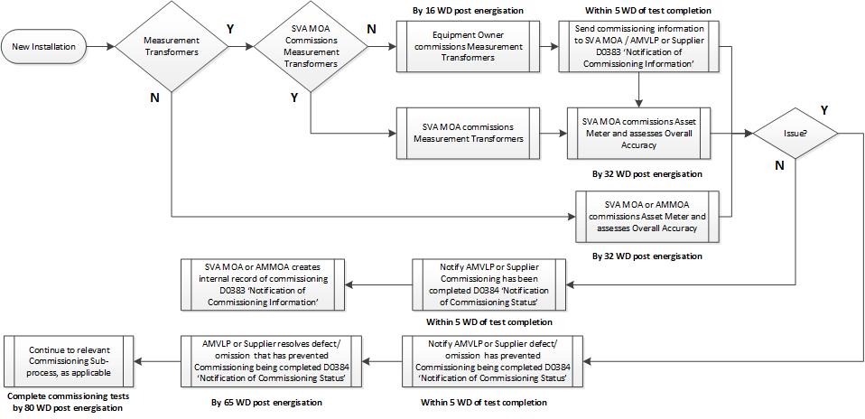
Figure 4 shows the high-level process for the commissioning of an Asset Metering System.
Figure 4: Commissioning Process for an Asset Metering System
Commissioning Process – Existing Installation
An existing Asset Metering System is one that has not been used in Settlement but has been used for other purposes, for example, the Electricity Market Reform Capacity Market or a relevant Balancing Service with the National Grid Electricity System Operator. An existing Metering System must be compliant with CoP11 to be used as an Asset Metering System. Where it is not the Asset Metering System may require to be replaced and/or commissioned as per the new installation process.
The AMVLP or Supplier will request confirmation of compliance as an Asset Metering System from the SVA MOA or AMMOA, as applicable (where measurement transformers are part of the Asset Metering System this can only be done by a SVA MOA). The AMVLP or Supplier will send details of the site (P0315 ‘Provision of Site Technical Details’), the installed metering (D0268 ‘Half Hourly Meter Technical Details’), and commissioning information (D0383 ‘Notification of Commissioning Information’) to the SVA MOA or AMMOA.
The SVA MOA or AMMOA will assess whether the Asset Metering System is compliant with CoP11 and determine the overall accuracy of the Asset Metering System and risk to Settlement. The SVA MOA or AMMOA may have to request calibration certificates for Asset Metering Equipment from the AMVLP or Supplier to be able to carry out the overall accuracy determination.
The SVA MOA or AMMOA will notify the AMVLP or Supplier whether the Asset Metering System is compliant (D0384 ‘Notification of Commissioning Status’) flow. Where, in the opinion of the SVA MOA or AMMOA, the Asset Metering System is non-compliant they will also provide the reasons for non-compliance (P0318 ‘Metering Non-Compliance Notification’) to the AMVLP or Supplier.
It is the responsibility of the AMVLP or Supplier to take the necessary steps, in conjunction with the equipment owner where required, to resolve the issue. This may require parts of the Asset Metering System to be replaced and/or commissioned. Once the identified issue has been resolved, the AMVLP or Supplier should request a new assessment of the compliance of the Asset Metering System by the SVA MOA or AMMOA.
Where the resolution is the replacement of the entire Asset Metering System this should be treated like a new installation and that process should be followed.
A proving test is an end to end test performed by the installer of the Asset Meter to prove that primary energy recorded by the Asset Meter (for both main and check Asset Meters (should a check Asset Meter be installed)) over a Settlement Period is being transferred and accurately received by the HHDC or AMHHDC Settlement Instation.
For Half Hourly Integral Outstation Asset Meters which can only have a pulse multiplier of one as identified on the Elexon website (compliance and protocol approval list), a proving test is not required. For all other situations a proving test is required (e.g. pulse multipliers that are not one, metering data is not recorded in the Asset Meter in Settlement Period format (i.e. 30 minute periods) and Complex Sites)
Other reasons for a proving test for those Asset Meters that are subject to the requirement for a proving test are:
Following a change of HHDC, or AMHHDC, appointment but only in the event that the Meter Technical Details was manually intervened;
Following a change of SVA MOA, or AMMOA, appointment but only in the event that the Meter Technical Details was manually intervened;
Following a concurrent change of AMVLP or Supplier and HHDC, or AMHHDC, but only in the event that the Meter Technical Details was manually intervened;
When an Asset Metering System is reconfigured / replaced;
When there is a key field change (see below);
Where there has been a key field change (see below) whilst a site has been de-energised and the Asset Metering System becomes energised; or
Where a feeder is energised for the first time.
Outstation Id;
Asset Meter Id (serial number);
Outstation number of channels;
Measurement Quantity Id;
Asset Meter multiplier;
Pulse multiplier;
CT and / or VT Ratios; and
Access to Asset Metering Equipment at Password level 3.
It is up to the SVA MOA or AMMOA to decide which technique is to be used to collect data in conjunction with the HHDC and AMHHDC.
Examples of the techniques available to the SVA MOA or AMMOA to collect data for a proving test are:
Record the cumulative register reading over a Settlement Period while on site; or
Use the Asset Meter manufacturer’s software to download the metered data; or
Use software which has a relevant protocol approval in accordance with BSCP601 ‘Metering Protocol Approval and Compliance Testing’ to download the metered data.
The HHDC or AMHHDC will collect the Settlement Period data requested by the SVA MOA or AMMOA. The HHDC or AMHHDC then sends this metered data to the SVA MOA or AMMOA for comparison. Where they are unable to collect metered data for the Settlement Period requested, the HHDC or AMHHDC should send alternative Settlement Period metered data.
The SVA MOA or AMMOA will confirm to the HHDC or AMHHC as to whether the proving test has been passed or not.
To be able to complete the registration process for an AMSID the AMVLP or Supplier requires technical details on the Asset Meter that has been installed by the SVA MOA or AMMOA. The HHDC or AMHHDC also need technical details about the Asset Metering System to be able to communicate with the Asset Meter and extract data to be used in Settlement.
The D0268 (‘Half Hourly Meter Technical Details’) flow is the primary electronic data flow between the SVA MOA or AMMOA and the HHDC, and AMHHDC (if applicable) and the AMVLP or Supplier for Half Hourly Meter Technical Details. Where an AMVLP or Supplier and AMVLP or Supplier Agent have a Data Transfer Network gateway use existing Data Flows to communicate but the option will be available to use other means (‘P’ Flows).
In the D0268 the J0418 data item (‘Meter CoP’), which is the reference to indicate which CoP the Metering System is configured, should be populated as ‘N’ as CoP11 and the relevant Asset Metering Type is not part of the valid set.
Following receipt of the D0268 the AMVLP or Supplier will send the P0303 Asset Meter Registration to the SVAA to complete Registration, and to the HHDC, and AMHHDC (if applicable) to notify them of the Asset Metering Type that the Asset Metering System is.
The AMVLP or
Supplier can check that an
Outstation Type ID, provided by the SVA MOA or AMMOA in the D0268, is valid by confirming that it is available for the relevant
Asset Metering Type on the
CoP Compliance and Protocol Approvals list. On the list, there is a column for the ‘Data Transfer Network Data Item J0471
Outstation Type’ that gives the three character code for a particular
Meter Type and Model.
For an
Asset Meter approved for use in
Code of Practice 1, 2, 3, 5 and 10 that is a Half Hourly Integral
Outstation Meter check the
Code of Practice that the
Meter has been approved for matches the relevant
Asset Metering Type (refer to
Asset Meters section table 1 for equivalence between
Asset Metering Types and
Code of Practice 1, 2, 3, 5 and 10). For all other types of
Asset Meter, refer to the
Asset Meter specific section of the
CoP Compliance and Protocol Approvals list.
Prior to installation of the Asset Meter, the SVA MOA or AMMOA may need to request site technical details (via a D0170) the AMVLP or Supplier will provide the information using the P0315 ‘Provision of Site Technical Details’ flow. This will include supply capacity, CT and VT details, and supply voltage for the relevant AMSID.
Data Submission and Transfer
Where Energy Market Architecture Repository (EMAR) Market Messages (“D-flows”) are referenced, these shall normally be sent over the Data Transfer Network (DTN). Where agreed between the relevant parties or where this is not possible, another method of transfer shall be agreed between the relevant parties, and the information transferred shall have the same content and format as it would if being transferred using the DTN.
AMHHDCs will not be recognised by the DTN, so should send data to HHDCs using an alternative method agreed with the HHDC.
AMMOAs will not be recognised by the DTN, so should send flows to AMVLPs, Suppliers, HHDCs, AMHHDCs and other AMMOAs/SVA MOAs using an alternative method agreed between the relevant parties.
Where a data flow includes the J0003 (‘MPAN Core’) data item it must be the AMSID that is used for this data item.
Metered volumes submitted must be in kilo Watt Hours (kWh). The method of transfer is the D0390 (’Asset Metering System Half Hourly Metered Data’) data flow, or an equivalent alternative method as agreed between the parties. Where the rated capacity of the circuit requires the Asset Meter to record energy in Mega Wh (MWh) (i.e. the primary measurement transformer ratios prevent the Asset Meter recording in kWh due to memory constraints) the data must be converted to kWh for submission to the HHDC and the SVAA. This can be completed by using the pulse multiplier data item.
The pulse multiplier is the factor required to adjust the pulses collected by the Asset Meter to the appropriate measured quantity required by the data collector and the SVAA (i.e. kWh). The typical value of the factor is dependent on the Asset Meter programming. For converting MWh to kWh the MWh values shall be multiplied by a factor of 1000.
The AMVLP or Supplier shall be responsible for producing a Single Line Diagram that must include and identify:
Boundary Point Metering System Identifiers (i.e. Import Meter Point Administration Number (MPAN) and Export MPAN if applicable);
Asset Metering Systems Ids (i.e. Import AMSID and Export AMSID if applicable);
Site dependent and independent load; and
Locations of all Metering Systems (Boundary Point Metering System(s) and Asset Metering System(s)).
No Single Line Diagram is required for Asset Metering Type 4 installations that are whole current or Asset Metering Type 5 installations.
For a high level example of a Single Line Diagram showing the location of all the Metering Systems refer to Figure 3 (Multiple Asset Metering Systems physical location (demand Asset)) in the Introduction (Background) section.
Compliance and Protocol Approval for Asset Meters
All Asset Meters must be approved for use in Settlement for them to be allowed to be registered against an AMSID. The process to achieve this is Compliance Testing and this is an assessment of compliance to the relevant Asset Metering Type in Code of Practice 11.
There is an existing Compliance Testing process in
BSCP601 - Metering Protocol Approval and Compliance Testing for
Half Hourly Meters and
Outstations and where a
Meter is approved for
Code Practice 1, 2, 3, 5 and 10 the relevant
Meter is automatically
approved for use in the equivalent
Asset Metering Type (refer to table 1
Asset Metering Type /
Code of Practice equivalence). This is
not reciprocated for
Asset Meters that have completed Compliance Testing (i.e. an
Asset Meter approved for
Asset Metering Type 1
cannot be used in a
Code of Practice 1 site unless it has completed Compliance Testing for
Code of Practice 1 as well).
All data collectors must have completed Protocol Approval testing for each type of Asset Meter they wish to be a data collector for. Each data collector intending to collect data from a new Asset Meter would require a separate Protocol Approval. This is applicable to both AMHHDCs and HHDCs, but where the HHDC is only receiving data from an AMHHDC the HHDC does not need to have Protocol Approval for the relevant Asset Meter, only the AMHHDC must have Protocol Approval.
Any HHDC with Protocol Approval for a compliant Meter approved for Code Practice 1, 2, 3, 5 and 10 is automatically approved to be appointed to an Asset Metering System using that Meter Type as an Asset Meter.
An Asset Meter is only allowed to be used in Settlement once it has completed Compliance Testing and at least one data collector has completed Protocol Approval.
The Compliance Testing and Protocol Approval has been extended to Asset Meters in Code of Practice 11 that are not compliant with Code Practice 1, 2, 3, 5 and 10. The two categories of Asset Meter that this is applicable to are:
An Asset Meter whose primary purpose is the measurement of Active Power and/or Active Energy that is not an approved Half Hourly Integral Outstation Meter compliant with Code Practice 1, 2, 3, 5 and 10; and
An Asset Meter whose primary purpose is not the measurement of Active Power and/or Active Energy and is not a Half Hourly Integral Outstation Meter. These Embedded Metering Devices are embedded within equipment used for purposes other than the measurement of Active Power and/or Active Energy, such as an EV charging unit or a small-scale domestic battery storage unit.
Applications for Compliance Testing are made against a particular Asset Metering Type, these are defined in CoP11 and can be found in the Asset Metering Types section of this guidance.
Compliance Testing shall be performed by an independent test laboratory and in order for them to do that the Applicant shall provide a minimum of two samples of the chosen Asset Meter and any supporting software and hardware necessary to fulfil testing
Where an Asset Meter is being submitted against multiple Asset Metering Types this shall be made clear in the application and the samples provided shall be for the highest accuracy class (e.g. if application for Asset Metering Types 1, 2 and 3 a class 0.2/0.2S Asset Meter should be provided).
Applications are made using
BSCP601 Form F601/03 and are normally made by the manufacturer of the meter. Compliance Testing confirms whether an
Asset Meter performs to the required accuracy and external influences (e.g. Electromagnetic compatibility and immunity to electromagnetic high frequency fields) do not affect it. It also confirms that the functionality is in accordance with the relevant type of
Asset Meter specified in
Code of Practice 11.
The process and required tests the compliance testing body needs to perform for Compliance Testing is set out in
BSCP601. The
Asset Meter must pass all the relevant tests. If the testing is successful, Elexon will issue a certificate of compliance to the applicant, on behalf of the BSC
Panel, against the relevant issue of a CoP11 for the relevant
Asset Metering Type.
Before testing can begin, Elexon and the manufacturer must agree the test schedule to ensure that it is relevant to the product in question. Failure to do so could result in test failures. Elexon also recommends that a manufacturer satisfy itself that the Asset Meter would meet all the requirements set out in CoP11 for the relevant Asset Metering Type, and the relevant tests for CoP11 Asset Meters in BSCP601, prior to applying for Compliance Testing approval.
In order to carry out Protocol Approval testing the relevant HHDC or AMHHDC requires sample Asset Meters. The testing involves setting up the sample Asset Meters on a test bench with an injected load; simulating certain events (e.g. clock trimming) and comparing the metered data collected using the manufacturer’s software with the metered data collected by the data collectors data collection software.
Applications for Protocol Approval are made using
BSCP601 Form F601/03 and are normally made by individual data collectors, although a manufacturer can do this if it chooses to. The HHDC or AMHHDC will agree a test schedule (i.e. on data retrieval, data security, time reset and data file creation) with Elexon and, when the HHDC or AMHHDC is ready, Elexon
will witness their tests. If the
Asset Meter passes all the tests then Elexon will issue a protocol certificate, to the applicant, on behalf of the BSC
Panel. The purpose of this certificate is to verify that the HHDC or AMHHDC has properly implemented the manufacturer’s protocol into its data collection system.
Once Compliance Testing has been completed and at least one HHDCs or AMHHDCs must have completed Protocol Approval Elexon will issue the relevant certificates (i.e. Certificate of Compliance (
BSCP601 Form F601/01) to the
Applicant; and Certificate of Protocol Approval (
BSCP601 Form F601/02) to HHDC or AMHHDC).
Elexon will update the
CoP Compliance Protocol Approval list of approved
Asset Meters and
Asset Meter data collectors on the Elexon website and also add the relevant
Asset Meter and HHDC / AMHHDC to the tables to allow AMVLPs or
Suppliers to register
Meter Technical Details (i.e.
Outstation Type) and appoint the relevant data collection Agent for an
AMSID.
Elexon will notify industry via a circular that a new Asset Meter has been approved or a new data collector has completed Protocol Testing
Registration of Assets, AMVLP or Supplier Agents and Asset Meters
An AMVLP or Supplier must complete a three stage registration process for Asset Metering Systems for an AMSID Pair to be allocated to a Secondary BM Unit at this point
1. Stage 1: Asset Registration;
2. Stage 2: AMVLP or Supplier Agent Registration; and
3. Stage 3: Asset Meter Registration.
Once all three stages have been completed and validated by the SVAA, the AMSID Pair can be allocated to a Secondary BM Unit by an AMVLP or used in an EMR AMSID declaration by a Supplier.
Stage 1: Asset Registration
The AMVLP or Supplier must provide Asset Registration details via Elexon Kinnect, either using direct screen input or by uploading a P0297 flow. The required data is:
AMVLP or Supplier Id;
Asset Registration Id - unique identifier for an Asset Registration for an AMVLP or Supplier;
AMSID Pair Effective from Date;
AMSID Pair Effective to Date;
Export AMSID required indicator – is the Asset capable of export and requires an Export AMSID?;
Import and Export (if applicable) AMSID – where existing AMSID Pair being amended;
Grid Supply Point (GSP) Group Id – GSP Asset is located i.e:;
BM Unit Id – (optional, to include Secondary BM Unit Id if available);
Address and postcode – Location of Asset;
Asset Type – the technology type that the Asset is (e.g. battery storage unit);
Asset Voltage – the voltage level (V) that the Asset is connected to (e.g. 11,000V);
Asset Capacity – the capacity in kW that the Asset is rated for;
Measurement Transformer Indicator – Does the Asset Metering System include measurement transformers? (i.e. current transformers and, if high voltage connection, voltage transformers);
Import and Export (if applicable) MSID(s) – for the Associated MSID Pair Boundary Point Metering System (i.e. Boundary Point MPAN(s));
The SVAA will validate these details and where Asset Registration fails validation the SVAA generates a Rejection of Asset Registration (P0298) file for download by the AMVLP; and where Asset Registration passes validation the SVAA generates a Confirmation of Asset Registration (P0298) file for download by the AMVLP or Supplier.
Stage 2: Asset Metering Party Agents
For the operation of Asset Metering Systems the AMVLP or Supplier must use Agents for the meter operations and data collection activities associated with Asset Metering Systems. AMVLPs or Suppliers are responsible for appointing qualified Agents to an AMSID.
The AMVLP or Supplier must only appoint Agents with whom it has agreed contractual terms to provide an Agent service for their Asset Metering portfolio or a particular AMSID.
Asset Metering is not a mandatory service that BSC Qualified Agents have to participate in.
The AMVLP or Supplier must appoint the same Asset Metering Party Agents (i.e. Meter Operator Agent and Data Collector) to both AMSIDs (i.e. Import and Export AMSIDs) in an AMSID Pair.
The AMVLP or Supplier must provide Registration of Asset Metering Party Agents details via Elexon Kinnect either by direct screen input or by uploading a P0300 flow. The required data is:
AMVLP or Supplier Id;
Import AMSID;
Export MSID – if applicable;
MOA Id – (SVA MOA or AMMOA);
MOA Effective from Date;
HHDC Id;
HHDC Effective from Date;
AMHHDC Id – if applicable;
AMHHDC Effective from Date – if applicable;
AMHHDC Effective to Date – if applicable.
The SVAA will validate these details and where Asset Metering Party Agents Registration fails validation the SVAA generates a Rejection of Asset Metering Party Agents Registration (P0301) file for download by the AMVLP or Supplier; and where Asset Metering Party Agent Registration passes validation the SVAA will generate a Confirmation of Asset Metering Party Agent Registration (P0302) file for download to the AMVLP or Supplier.
Asset Metering Party Agents fall into two categories:
1. Meter Operator Agents (MOA); and
The processes for these Asset Metering Party Agents for meter operations and data collection are defined in BSCP603 (Meter Operations and Data Collection for Asset Metering Systems) and split into five categories:
1. Registration Activities
Installation of new Asset Metering System;
Commissioning of a new Asset Metering System;
Using an existing Metering System as an Asset Metering System; and
Change of AMVLP or Supplier and/or Agent(s).
Energise / De-energise an Asset Metering System;
Removal of an Asset Metering System;
Reconfigure or Replace an Asset Metering System; and
Change of Asset Feeder status – Energise / De-energise.
HHDC collects directly
AMHHDC collects directly
HHDC or AMHHDC investigates inconsistencies
4. Asset Metering System Investigation Process
Where Energy Market Architecture Repository (EMAR) Market Messages (“D-flows”) are required to be sent between an AMVLP or Supplier and Asset Metering Party Agents, or between Asset Metering Party Agents, these shall normally be sent over the Data Transfer Network (DTN). Where agreed between the relevant parties or where this is not possible, another method of transfer shall be agreed between the relevant parties, and the information transferred shall have the same content and format as it would if being transferred using the DTN.
Meter Operator Agent (MOA)
The MOA is responsible for the installation, commissioning and maintenance of Asset Metering Systems where they have been appointed to an AMSID.
Where the Asset Metering System includes measurement transformers (i.e. Current Transformers or Voltage Transformers) a SVA Half Hourly (HH) MOA, referred to as a Metering Equipment Manager (MEM) in the Retail Energy Code (REC), can be appointed to any Asset Metering Type. A SVA MOA does not require to undergo any additional qualification to act as an Asset Metering Party Agents.
Where the Asset Metering System does not include measurement transformers an Asset Metering MOA (AMMOA) can be appointed. This is only applicable to Asset Metering Type 4, where the Asset Metering is whole current, and Asset Metering Type 5 installations. An AMMOA must have completed qualification under the BSC to act as an Asset Metering Party Agent.
For the avoidance of doubt, an SVA MOA can be appointed as an Asset Metering Party Agent for Asset Metering Type 4, where the Asset Metering is whole current, and Asset Metering Type 5 installations.
The Data Collector is responsible for the collection, validation, estimation and submission of data for Asset Metering Systems where they have been appointed to an AMSID.
A Half Hourly Data Collector (HHDC) must always be appointed as an Asset Metering Party Agent for an AMSID. The HHDC will always submit metered data to the SVAA. A HHDC does not require to undergo any additional qualification to act as an Asset Metering Party Agent.
In addition to a HHDC, an Asset Metering HHDC (AMHHDC) can be appointed as an Asset Metering Party Agent for an AMSID. The AMHHDC must submit metered data to the HHDC for onward submission to the SVAA. An AMHHDC must have completed qualification under the BSC to act as an Asset Metering Party Agent.
The HHDC must send the SVAA actual or estimated data by the SF (Initial) Volume Allocation Run. Where an AMHHDC has been appointed, the AMHHDC must send the HHDC actual or estimated date by three working days before the SF Volume Allocation Run.
Asset Metering System metered data must be sent from an AMHHDC to a HHDC by a D0390 (‘Asset Metering System Half Hourly Metered Data’) flow, or equivalent method. HHDCs must use a D0390 to send metered data to the SVAA.
HHDCs and AMHHDCs are not required to resend data for subsequent Volume Allocation Runs after submitting actual data, unless more accurate data has become available.
Stage 3: Asset Meter Registration
Once the appointed MOA has completed the installation of the Asset Meter and provided the details to the AMVLP or Supplier (via the D0268 ‘Half Hourly Meter Technical Details’ flow) the AMVLP or Supplier must provide Asset Meter Registration details via Elexon Kinnect, either by direct screen input or by uploading a P0303 flow. The required data is:
AMVLP or Supplier Id;
Import AMSID;
Export AMSID – if applicable;
Asset Meter Serial Number – (for Import & if applicable Export AMSID);
Outstation Type – (for Import & if applicable Export AMSID);
Asset Meter make and model – (for Import & if applicable Export AMSID);
Asset Meter Effective from Date - (for Import & if applicable Export AMSID);
Asset Meter Effective to Date - (for Import & if applicable Export AMSID); and
Asset Metering Type (i.e. 1, 2, 3, 4 or 5).
Elexon Kinnect will validate these details and where Asset Meter Registration fails validation a Rejection of Asset Meter Registration (P0304) file will be generated for download by the AMVLP or Supplier; and where Asset Meter Registration passes validation a Confirmation of Asset Meter Registration (P0305) file will be generated for download by the AMVLP or Supplier.
The AMVLP or Supplier may have to consult with the MOA where the rejection relates to an issue with the Outstation Id and the MOA may have to provide an amended D0268 ‘Half Hourly Meter Technical Details’ flow to the AMVLP or Supplier.
The
Outstation Type is an identifier for the type of
Asset Meter Outstation and is defined in the
CoP Compliance Protocol Approvals list. The
Outstation Type, and the
Asset Meter manufacturer’s make and model type reference is provided to the AMVLP or
Supplier from the MOA via the D0268 ‘Half Hourly
Meter Technical Details’ flow.
Where the
Outstation is not integral to the
Asset Meter the
Outstation Type ID and details for the
Outstation shall be used for Registration. Any
Asset Meter connected to a separate
Outstation must also be an approved device and be on the
CoP Compliance Protocol Approvals list.
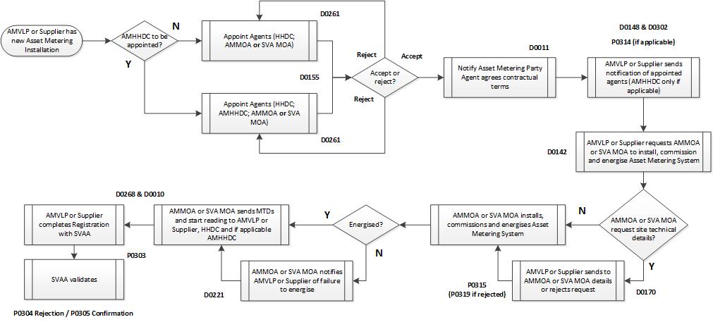
Figure 5 shows the high level process for the appointment of Asset Metering Party Agents and installation of an Asset Metering System through to the submission of the AMVLP or Supplier completing Stage 3 for the Registration process with the SVAA. For more detail on the commissioning sub-process refer to the commissioning process for new installation section and Figure 4.
Final Stage: Allocation to a Secondary BM Unit
Once registration stages one, two and three have been completed and validated by the SVAA, the AMSID Pair can be allocated to a Secondary BM Unit. The allocation details must include whether Asset Metering or Asset Differencing is used for the relevant AMSIDs. Only an AMVLP can allocate an AMSID to a Secondary BMU.
The AMVLP must allocate the Import AMSID, and if applicable Export AMSID, to the relevant Secondary BM Unit via Elexon Kinnect, either using direct screen input or by uploading a P0306 flow. The required data is:
AMVLP Id;
Secondary BM Unit ID
Import AMSID;
Export AMSID – if applicable;
AMSID Pair Differencing Indicator;
MSID Pair Indicator;
AMSID Pair in Secondary BM Unit Effective from Date;
AMSID Pair in Secondary BM Unit Effective to Date (Optional);
Import MSID (from Associated MSID Pair); and
Export MSID (from Associated MSID Pair, where present).
Figure 5: Asset Metering Party Agent appointment and Asset Metering System installation process
Asset Differencing and Complex Sites
Where there is more than one Asset located behind the Boundary Point Metering System, metered volumes for the Assets can be calculated using a new differencing process called Asset Differencing.
Asset Differencing is the process where metered data for an Asset is derived from the metered data of a Boundary Point Metering System (MPAN) and an Asset Metering System (AMSID) located behind the relevant Boundary Point Metering System. This is the responsibility of the AMVLP to arrange as part of the registration process.
An AMSID Pair will be registered by one AMVLP for Asset Metering, and subsequently used by another for Asset Differencing (or vice versa). The ‘differencing’ will be applied during aggregation of Metered Data up to a Secondary BM Unit level.
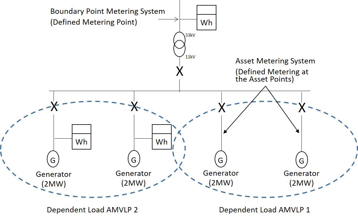
Figure 6 shows the use of Asset Differencing to determine the Dependent Load metered data values for AMVLP 1. The solution is reliant on using the Boundary Point Metering System and netting off the Asset Metering System installed by AMVLP 2 to determine the output of the Asset associated with AMVLP 1. When AMVLP 1 is completing the Registration process the Asset Differencing indicator will be set to true for their AMSIDs.
Figure 6: Asset Differencing Metering physical location of a second Asset
Where an Asset Metering System cannot be installed at the Asset for financial or practical reasons then Asset Meter(s) can be installed to measure the independent load of the site. In this scenario, the AMSID would be registered for the Asset providing the Balancing Service on site; however the SVAA will have to apply ‘Asset Differencing to derive the metered data for the Asset.
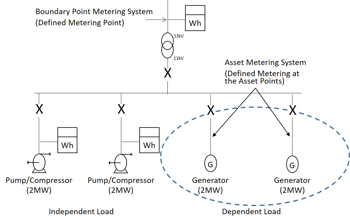
Figure 7 shows the use of Asset Differencing to determine the Dependent Load metered data values for an Asset. The solution is reliant on using the Boundary Point Metering System and netting off the Asset Metering System installed to measure the Independent Load of the site to determine the output of the Asset. When the AMVLP is completing the Registration process the Asset Differencing indicator will be set to true for their AMSIDs.
Figure 7: Asset Differencing Metering physical location of the Independent Load
Where an Asset is no longer used and is de-registered the remaining Asset, assuming only two Assets had been behind the Boundary Point Metering System in the arrangement, can revert back to using that Boundary Point Metering System (i.e. the MPAN) to identify the metered data of the Asset.
As such, Asset Differencing does not require an ‘Asset Metering Complex Site Supplementary Information Form’.
Complex Sites in relation to Asset Metering are limited to the application of fixed multipliers to account for losses incurred due to the location of the Asset Metering System where the Asset Meter is not capable of making the necessary adjustments.
In this scenario, an ‘Asset Metering Complex Site Supplementary Information Form’ must be submitted to enable the HHDC or AMHHDC to interpret the standing and dynamic metered data relating to the Asset Metering System. This is to be provided to the HHDC or AMHHDC in addition to the D0268, ‘Half Hourly Meter Technical Details’.
Form CoP11/Fa ‘Asset Metering Complex Site Supplementary Information Form’ provides a means for the SVA MOA or AMMOA to convey the information necessary for correct aggregation. CoP11/Fa shows the information needed to collect that data.
The D0268 is primary electronic data flow between the SVA MOA or AMMOA and the HHDC, and AMHHDC (if applicable) for Half Hourly Meter Technical Details. The ‘Asset Metering Complex Site Supplementary Information Form’ supplements the D0268 and instructs the HHDC or AMHHDC how to apply a fixed multiplier to the various channels of data that should be utilised in Settlements. The HHDC or AMHHDC (as applicable) will run the aggregation rule specified in the ‘Asset Metering Complex Site Supplementary Information Form’ to apply the fixed multiplier to the metered data measured by the Asset Meter.
The SVA MOA or AMMOA identifies a site as complex by setting the ‘Complex Site Indicator’ (J1687) in the D0268 to True. The HHDC or AMHHDC will then expect to receive, or have already received, an ‘Asset Metering Complex Site Supplementary Information Form’ from the SVA MOA or AMMOA. The ‘Asset Metering Complex Site Supplementary Information Form’ shall be sent no later than, or preferably in advance of, the sending of the D0268 data flow. The ‘Asset Metering Complex Site Supplementary Information Form’ should be sent electronically or by any other method agreed.
The AMVLP or Supplier should identify to the SVA MOA or AMMOA which AMSIDs relate to the Import energy and which AMSIDs relate to the Export energy. It is the responsibility of AMVLPs or Suppliers to manage and co-ordinate their Agents to achieve compliance and to intervene should any issues arise.
In some cases, a Complex Site for
Asset Metering Systems shall meet the conditions required to apply for a
Metering Dispensation as described in
BSCP32 ‘Metering Dispensations’. Where Complex Sites use
Asset Metering Systems that are not fully compliant with CoP 11, a
Metering Dispensation should be applied for via
BSCP32. Once a
Metering Dispensation has been granted, the information shall be available for all future AMVLPs or
Suppliers, so that they shall have the ability to understand the metering configuration at the Complex Site. As part of the dispensation application process, the AMVLP or
Supplier shall need to submit a simplified schematic diagram of the Complex Site connection arrangements and the proposed metering points, as required in
BSCP32.
There are two situations where an adjustment for losses can be made using an ‘Asset Metering Complex Site Supplementary Information Form’:
System Losses – Where the Asset Meter is subject to a Metering Dispensation and is not located at the Defined Metering at the Asset Point and an electrical loss factor has been applied to account for equipment and cabling between the Actual Metering at the Asset Point and the Defined Metering at the Asset Point; and
Inverter and Rectifier Losses – Where the location of the Asset Meter, where it is Asset Metering Type 5, is in such a place that it does not account for the losses of the inverter or rectifier.
For example, where the AMSID is 7734567890111 and the losses between the Actual Metering at the Asset Point and the Defined Metering at the Asset Point have been calculated as 2% the aggregation rule would be:
7734567890111 = [7734567890111 Asset Meter identifier and channel details] x 1.02
An adjustment for losses should be done for both the Import AMSID and the Export AMSID should the Asset Meter be configured to record both Asset Import and Asset Export.
For more information please contact the BSC Service Desk or call 0370 010 6950.
Intellectual Property Rights, Copyright and Disclaimer The copyright and other intellectual property rights in this document are vested in Elexon or appear with the consent of the copyright owner. These materials are made available for you for the purposes of your participation in the electricity industry. If you have an interest in the electricity industry, you may view, download, copy, distribute, modify, transmit, publish, sell or create derivative works (in whatever format) from this document or in other cases use for personal academic or other non-commercial purposes. All copyright and other proprietary notices contained in the document must be retained on any copy you make. All other rights of the copyright owner not expressly dealt with above are reserved. No representation, warranty or guarantee is made that the information in this document is accurate or complete. While care is taken in the collection and provision of this information, Elexon Limited shall not be liable for any errors, omissions, misstatements or mistakes in any information or damages resulting from the use of this information or action taken in reliance on it. |