Balancing and Settlement Code
CODE OF PRACTICE FOR THE METERING OF ENERGY IMPORTS VIA LOW VOLTAGE CIRCUITS FUSED AT 100 AMPS OR LESS PER PHASE FOR SETTLEMENT PURPOSES
CODE OF PRACTICE FOR THE METERING OF ENERGY IMPORTS VIA LOW VOLTAGE CIRCUITS FUSED AT 100 AMPS OR LESS PER PHASE FOR SETTLEMENT PURPOSES.
1. Reference is made to the Balancing and Settlement Code for the Electricity Industry in Great Britain and, in particular, to the definition of "Code of Practice" in Annex X-1 thereof.
2 This is Code of Practice Six, Issue 4, Version 9.0.
3. This Code of Practice shall apply to Metering Systems comprising Metering Equipment that are subject to the requirements of Section L of the Balancing and Settlement Code.
4. This Code of Practice is effective from 1 September 2021.
5. This Code of Practice has been approved by the Panel.
ISSUE | DATE | VERSION | CHANGES | AUTHOR | APPROVED |
1 | 29/01/96 | 3.00 | Approved by MDC | 1998 MTF | MDC, 10/01/96 |
2 | 18/11/96 | 3.10 | Approved by MDC | MDC | MDC |
3 | 22/01/98 | 4.10 | Protocol amended | MDC | MDC, 22/01/98 |
4 | 01/12/98 | 4.20 | Protocol amended | JKHC | TS2, 11/11/98 |
4 | Code Effective Date | 4.20 | Re-badging of Code of Practice Six for the implementation of the Balancing and Settlement Code | BSCCo | Panel 16/11/00 (Paper 07/003) |
4 | BETTA Effective Date | 5.0 | BETTA 6.3 for the SVA February 2005 Release | BSCCo | SVG/48/004 |
4 | 06/11/08 | 6.0 | CP1238 November 08 Release | BSCCo | ISG88/01 SVG88/02 |
4 | 25/06/09 | 7.0 | CP1264 June 09 Release | BSCCo | ISG94/01 SVG94/02 |
4 | 26/11/09 | 8.0 | Modification P230 | BSCCo | Panel |
4 | 01/09/21 | 9.0 | P420 – 1 September 2021 Non-Standard Release | BSCCo | Panel 316/05 |
Intellectual Property Rights, Copyright and Disclaimer The copyright and other intellectual property rights in this document are vested in Elexon or appear with the consent of the copyright owner. These materials are made available for you for the purposes of your participation in the electricity industry. If you have an interest in the electricity industry, you may view, download, copy, distribute, modify, transmit, publish, sell or create derivative works (in whatever format) from this document or in other cases use for personal academic or other non-commercial purposes. All copyright and other proprietary notices contained in the document must be retained on any copy you make. All other rights of the copyright owner not expressly dealt with above are reserved. No representation, warranty or guarantee is made that the information in this document is accurate or complete. While care is taken in the collection and provision of this information, Elexon Limited shall not be liable for any errors, omissions, misstatements or mistakes in any information or damages resulting from the use of this information or action taken in reliance on it. |
This Code of Practice defines the minimum requirements for Direct Connected Metering Equipment at the point of connection and or supply FOR THE METERING OF ENERGY VIA LOW VOLTAGE CIRCUITS FUSED AT 100 AMPS OR LESS PER PHASE.
BSCCo shall retain copies of, inter alia, the Code of Practice together with copies of all documents referred to in them, in accordance with the provisions of the Balancing and Settlement Code (“the Code”).
This Code of Practice states the practices that shall be employed, and the facilities that shall be provided for the measurement and recording of the quantities required for Settlement purposes.
This Code of Practice specifically applies to Direct Connected Metering Equipment to be installed FOR THE METERING OF ENERGY IMPORTS VIA LOW VOLTAGE CIRCUITS FUSED AT 100 AMPS OR LESS PER PHASE.
Reactive energy measurement is not specifically covered within this Code, where kVA and/or kvar are required Code of Practice Five equipment shall be used.
It will be noted that this Code of Practice and Code of Practice Seven apply to the same circuit consumption. For clarity the distinction is that Code of Practice Six sets out the requirements for Settlement Metering Equipment and Code of Practice Seven specifies the settlement requirements as part of a wider metering and data collection infrastructure providing data to the Data Processing Interface. Code of Practice Seven does not require Code of Practice Six Meters to be used. It would however be possible to construct a Code of Practice Seven system using Code of Practice Six Metering.
The Metering Equipment shall be categorised into polyphase and single phase metering and one of the following types, dependent upon the period for which the equipment is able to record the Settlement information:
i) Code of Practice Six (a) - minimum storage period of 20 days;
ii) Code of Practice Six (b) - minimum storage period of 100 days;
iii) Code of Practice Six (c) - minimum storage period of 250 days; or
iv) Code of Practice Six (d) - minimum storage period of 450 days.
This Code of Practice derives force from the metering provisions of the Code and in particular Section L, to which reference should be made and should also be read in conjunction with the relevant BSC Procedures for, inter alia, operation of the data collection systems.
Metering Equipment that meets the requirements of this Code of Practice is also applicable where the Registrant is required by its Supply Licence (and as referenced in Section L3.2.6) to install Metering Equipment that is capable of providing measured electricity consumption data for multiple periods (at least half hourly) and providing the Registrant with remote access to such data.
This Code of Practice does not contain the calibration, testing and commissioning requirements for Metering Equipment used for Settlement purposes. These requirements are detailed in Code of Practice Four - "Code of Practice for Calibration, Testing and Commissioning Requirements for Metering Equipment for Settlement Purposes".
Dispensations from the requirements of this Code of Practice may be sought in accordance with the Code and BSCP32.
Meters and Outstations referred to in this Code of Practice shall only achieve successful compliance in respect of any testing detailed in this Code of Practice if the requirements set out in accordance with BSCP601 are also observed and successfully completed or the Registrant has been granted a valid Metering Dispensation covering any departure from the requirements as detailed in this Code of Practice.
In the event of an inconsistency between the provisions of this Code of Practice and the Code, the provisions of the Code shall prevail.
The following documents are referred to in the text;
BS EN 61036 | AC Static Watt-hour Meters for Active Energy (Classes 1 and 2). |
BS EN 60521 | Specification of Class 0.5, 1 and 2 Single-Phase and polyphase, single rate and Multi rate Watt hour meters. |
SI 792 | The Meters (Certification) Regulations 1990. |
Electricity Act 1989 | Schedule 7, as amended by the schedule 1, to the Competition and Services (Utilities) Act 1992. |
BS EN 61107 | Data Exchange for Meter Reading, Tariff and Load Control. Direct Local Exchange. |
IEC 1334-4-41 | Application Protocols: Distribution Line Message Specification. |
Balancing and Settlement Code | Section X; Annex X-1 and BSC Procedures. |
Code of Practice 4 | Code of Practice for Calibration, Testing and Commissioning Requirements for Metering Equipment for Settlement Purposes. |
Code of Practice 5 | Code of Practice for the Metering of Energy Transfers with a Maximum Demand of up to (and Including) 1MWfor Settlement Purposes. |
Code of Practice 7 | Code of Practice for Metering of Energy Imports via Low Voltage Circuits Fused at 100Amps or Less per Phase for Settlement Purposes. |
4. DEFINITIONS AND INTERPRETATIONS
Save as otherwise expressly provided herein, words and expressions used in this Code of Practice shall have the meanings attributed to them in the Code and are included for the purpose of clarification.
Note: * indicates definitions in the Code.
Note: † indicates definitions which supplement or complement those in the Code.
Note: ‡ indicates definitions specific to this Code of Practice
Active Energy means the electrical energy produced, flowing or supplied by an electrical circuit during a time interval, and being the integral with respect to time of the instantaneous Active Power measured in units of watt-hours or standard multiples thereof;
Active Power means the product of voltage and the in-phase component of alternating current measured in units of watts and standard multiples thereof, that is;
Demand Period means the period over which Active Power is integrated to produce Demand Values. Each Demand Period shall be of 30 minutes duration, one of which shall finish at 24:00 hours.
Demand Values means, expressed in kW twice the value of kWh recorded during any Demand Period. The Demand Values are half hour demands and these are identified by the time of the end of the Demand Period.
"electricity" means Active Energy and Reactive Energy.
4.6 Energy Storage Device ‡
A device to provide standby power to the Metering Equipment clock in the event of mains failure. e.g. battery or super capacitor.
Full Load means the product of the number of phases, maximum current (Imax), and rated voltage of the Meter at unity power factor
Import means, for the purposes of this Code of Practice, an electricity flow as specified within the Code.
Interrogation Unit means a Hand Held Unit "HHU" (also known as Local Interrogation Unit "LIU") or portable computer which can program Metering Equipment parameters and extract information from the Metering Equipment and store this for later retrieval.
Maximum Demand expressed in kW means twice the greatest number of kWh recorded during any Demand Period.
Means a device for measuring electrical energy.
4.12 Metering Equipment *
Metering Equipment means Meters, measurement transformers (voltage, current and combination units), metering protection equipment, including alarms, circuitry, associated Communications Equipment and Outstations and wiring.
Meter Register means a device, normally associated with a Meter, from which it is possible to obtain a reading of the amount of Active Energy that has been supplied by a circuit.
Outstation means equipment which receives and stores data from a Meter(s) for the purpose, inter alia, of transfer of that metering data to the Central Data Collector Agent (CDCA) or Data Collector as the case may be, and which may perform some processing before such transfer and may be in one or more separate units or be integral with the Meter.
Password means a string of characters of length 6 characters, where each character is a case insensitive or sensitive alpha character (A to Z), a digit (0 to 9), the underscore character (_) or a hexadecimal password (0 to F). The characters of a hexadecimal password must be in upper case.
Outstation System means one or more Outstations linked to a single communication line.
PSTN means the public switched telephone network.
Registrant means, in relation to a Metering System, the person for the time being registered in CMRS or (as the case may be) SMRS in respect of that Metering System pursuant to Section K of the Balancing and Settlement Code.
4.19 Settlement Instation ‡
Settlement Instation means a computer based system which collects or receives data on a routine basis from selected Outstation by the Central Data Collector or (as the case may be) a relevant Data Collector.
Means a person to whom electrical power is provided, whether or not that person is the provider of that electrical power; and where that electrical power is measured by a SVA Metering System.
UTC means Co-ordinated Universal Time which bears the same meaning as in the document Standard Frequency and Time Signal Emission, International Telecommunication Union - RTF.460(ISBN92-61-05311-4) (colloquially referred to as Rugby Time).
For each circuit the following energy measurements are required for Settlement purposes:
5.2 Accuracy Requirements
The overall accuracy of the energy measurements shall at all times be within the limits of error specified in SI 792 Regulation 8 pertaining to Schedule 7 of the Electricity Act 1989.
Meters, where certified, shall be certified in accordance with schedule 7 of the Electricity Act 1989.
Appropriate evidence to substantiate that these overall accuracy requirements are met shall be available for inspection to Pool Members or their agent(s).
6. METERING EQUIPMENT CRITERIA
Although for clarity this Code of Practice identifies separate items of equipment, nothing in it prevents such items being combined to perform the same task provided the requirements of this Code of Practice are met. Where separate items of equipment are provided they shall be individually protected against electrical overload.
All Metering Equipment (including any Energy Storage Device) shall have a minimum design service life, without maintenance, of 10 years from date of manufacture.
For each circuit direct connected Active Energy Meters shall be used in accordance with Schedule 7 of the Electricity Act 1989.
New Meters shall comply with the requirements of either BS EN 61036 Class 2, for indoor meters or BS EN 60521 Class 2. The rating for single phase meters shall be 230 volts, 50Hz, 20 Amps basic or less and 100 Amps maximum and for polyphase meters 230/400 volts, 50Hz, 40 Amps basic or less and 100 Amps maximum current.
Existing meters may be used provided they were manufactured to the relevant British Standards. Ratings different to those quoted for new meters may be utilised provided they are appropriate for the supply being metered.
Meters which provide data to separate Outstations shall provide an output for this purpose.
An Outstation System shall be provided which transfers data to and receives data from a Settlement Instation(s). Outstations shall comply with all relevant requirements contained within BS EN 61036 for indoor conditions.
Separate Outstations storing data from a number of different circuits, up to a maximum consumption of 1GWh, and Meters with integral Outstation facilities may be cascaded onto one communication channel.
Metering data will normally be collected by the Settlement Instations in accordance with the following time scales, dependent upon which category of Metering Equipment that has been installed:
a) Code Six (a) - daily interrogation;
b) Code Six (b) - up to monthly interrogation;
c) Code Six (c) - up to quarterly interrogation; or
d) Code Six (d) - up to yearly interrogation.
Repeat collections of metering data shall be possible throughout the Outstation data storage period.
The Outstation shall have the ability to allow the metering data to be read by Instations other than the Settlement Instation provided the requirements of Section 8 of this Code of Practice are satisfied.
For the purpose of transferring stored metering data from the Outstation to the Settlement Instation, a unique Outstation identification code shall be provided.
Where an Outstation has a primary battery to provide back-up for the clock and calendar, this battery shall have a minimum standby service life of 3 years from the date of manufacture of the Outstation i.e. supporting the clock for 3 years without mains power.
Where Energy Storage Devices other than primary batteries are used, the clock and calendar shall be supported for a period of 7 days without an external supply connected to cater for extended supply failure.
In the event of an Outstation supply failure, the Outstation shall retain all data stored up to the time of the failure, and maintain the time accuracy in accordance with paragraph 6.2.2. These time accuracy requirements do not apply where the Outstation clock is re-synchronised from a broadcast clock when re-energised. (refer to section 6.2.3.)
Any "reading" or "reprogramming" operation shall not delete or alter any stored energy consumption data or associated alarms.
Where the Outstation is storing data for more than one circuit it shall continue to operate while any one circuit is energised.
The Outstation shall be clearly marked with the relevant part of Code of Practice 6. i.e. a, b, c or d.
6.2.1 Data Provision requirements
This section sets out the data to be provided by the Outstation and the duration of storage required. For the avoidance of doubt all Metering data shall be output in engineering units i.e. kWh.
Data shall be provided as follows and is specifically defined in Appendix 1.
(i) For Each Interrogation of the Outstation the data provided shall be:
The meter identifier 12 characters alphanumeric as defined in Appendix 1b. Where a separate Outstation is used the channel ID shall be the meter ID;
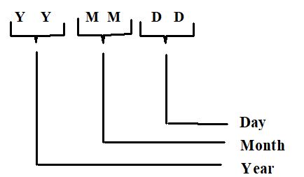
The date and time of interrogation [YYMMDDhhmmss];
kWh cumulative total meter advance register value for each Meter to 6 digit integer kWh value padded with leading zeroes where appropriate;
For polyphase metering Maximum Demand (MD), 6 digit (4 integer and 2 decimal places) kW value, padded with leading zeros where appropriate, for each meter for both the current and previous programmable charging period e.g. monthly, statistical review period, as required by the Supplier, and cumulative Maximum Demand;
date of Maximum Demand reset [YYMMDD];
number of Maximum Demand resets;
multi-rate cumulative Active Energy registers as specified by Supplier; and
number of days data returned from the meter.
(ii) The Outstation shall provide the following information for each Day and for the current day up to the time of interrogation:
Calendar day date [YYMMDD];
kWh cumulative total register value for each Meter to 8 digit (including 2 decimal place) kWh value padded with leading zeroes where appropriate;
Where a battery is fitted, a battery change maintenance flag shall be provided based on standby battery service life;
An indication should clock failure occur e.g. When the system clock has failed due to power or battery failure;
The number of level 2 successful password accesses made on that day to a maximum of 7;
MD reset flag as appropriate; and
A flag to indicate a power outage for the whole of a Settlement Day.
(iii) For each Demand Period the Outstation will provide, for each Meter:
Truncated absolute cumulative register reading in the range 10’s of kWh, kWh, 1/10 kWh and 1/100 kWh;
A flag to indicate if net reverse energy flow has taken place over all phases;
A flag to indicate successful level 2 password access; and
A flag to indicate that the power supply to the Outstation has failed.
A data capacity of 48 periods per day for the number of days specified below dependent upon the category of Metering Equipment shall be provided:
Code of Practice Six (a) - minimum storage period of 20 days;
Code of Practice Six (b) - minimum storage period of 100 days;
Code of Practice Six (c) - minimum storage period of 250 days; or
Code of Practice Six (d) - minimum storage period of 450 days.
Where the prescribed data storage period is exceeded the meter shall begin to wrap data i.e. replace the first reading with that of the latest reading.
The value of energy measured in a Demand Period but not stored in that Demand Period shall be carried forward to the next Demand Period.
Any discrepancy between the measured value of Active Energy at each individual metering point and the equivalent data presented by the Outstation for the same metering point shall not exceed +/- 0.5% at full load at that metering point.
An Outstation shall provide any portion of the data stored upon request by an Instation.
(i) The Outstation time shall be set to the Universal Time Clock (UTC). No switching between UTC and British Summer Time (BST) shall occur for settlements data storage requirements.
Routine time synchronisation may be carried out using 30 minute synchronising pulses or broadcast clocks up to a maximum limit of +/- 1 second per Demand Period without setting any password access flags.
The clock of the Outstation shall be capable of being set or adjusted using the local or remote communication ports but only once during any demand period.
(ii) The overall limits of error for the time keeping shall be:
The completion of each Demand Period shall be at a time which is within ± 6 minutes of UTC; and
The duration of each Demand Period shall be within ± 0.6%, except where time synchronisation has occurred in a Demand Period.
The variation in the completion of each Demand Period shall not exceed 20 seconds over 20 day period.
6.2.3 Monitoring Facilities - Broadcast Clocks
(i) For complete power outages up to 3 seconds in duration, the real time clock shall continue without interruption. This power outage event shall not cause the power outage flag or the successful level two password flag to be set at the time of power restoration.
(ii) For power outages longer than three seconds and where power has now been restored, the clock shall start and continue from the time of failure until the broadcast clock is detected and successfully decoded, within the normal operating constraints of the broadcast clock system, the clock shall reset to UTC and the power failure flag and successful level two access password flag shall be set for the returning Demand Periods where the power outage existed.
(iii) Where the broadcast clock cannot be detected by the Outstation, within the normal operating constraints and messaging protocols of the broadcast clock system, the clock failure flag shall be set for that day. The Outstation shall continue to maintain system clock accuracy as detailed in section 6.2.2. of this code of practice in the absence of the broadcast clock.
6.3 Displays and Facilities
The Metering Equipment shall display the following information (not necessarily simultaneously):
total Import cumulative kWh per circuit, 6 digit integer kWh value padded with leading zeroes where appropriate for polyphase and 5 digit integer kWh value padded with leading zeroes where appropriate for single phase Meters; and
current UTC or clock time and date as defined by the supplier.
The Metering Equipment shall be capable of enabling the display of the following information:
(i) For polyphase meters:
Maximum Demand ("MD") in 6 digit (4 integer and 2 decimal places) kW value padded with leading zeroes where appropriate for the current and historic programmable charging period;
twice the kWh advance since the commencement of a current Demand Period, (i.e. "kW rising demand") to 6 digits (4 integer and 2 decimal places) kW value padded with leading zeroes where appropriate for the current and historic programmable charging period;
cumulative MD, 6 digit (4 integer and 2 decimal places) kW value padded with leading zeroes where appropriate;
the last two digits of the number of MD resets (99 rollover to zero); and
multi-rate display sequence as specified by Supplier, with a minimum of 8 registers selectable over the calendar year. Further details are set out in Appendix 4.
(ii) For single phase meters:
Where a multi-rate display sequence is enabled on a Meter, the default display shall be the cumulative kWh register of the active rate and the rate identifier. The initial operation of the display selector shall display the test display and the next operation shall display the total Import cumulative kWh. Subsequent operation of the display selector shall display registers in a sequence specified by the supplier.
The Outstation shall always provide local interrogation facilities via an accessible port.
6.4.1 Local Interrogation
An interrogation port shall be provided:
• Physically: shall be an optical port to BS EN 61107;
• Data Protocol: Standard as defined in Appendix 1 (a and b), Appendix 2 (a and b) and Appendix 3.
The outline Data structure for the information required in 6.2.1. is detailed in Appendix 1a.
The detailed application data structure and format for the data items specified in section 6.2.1. is detailed in Appendix 1b.
The data definitions and descriptions are detailed in Appendix 2a. The functional overlay specified in section 6.4.3. is detailed in Appendix 2b (protocol examples).
The Outstation shall have a maximum transfer time of 90 seconds per 100 days for each Meter through the local data port for the data specified above.
6.4.2 Remote Interrogation
Where a remote interrogation facility is provided it shall not be possible to disconnect this link at the Outstation without the breaking of a seal.
The data shall be to the standard data structure as set out in Appendix 1b.
The protocol shall be standard for all Outstations for the following settlement functions for the data specified in 6.2.1:
• Read complete 30 minute database, (see note below and 11.2.3);
• Last ‘n’ days of data, where ‘n’ is the number of days (n = 1 is the current day);
• Read selected Meters (if appropriate);
• Change Authentication key at level 2 password access.
Note: The complete 30 minute database can be read by setting ‘n’ (number of days) to a value equal to or greater than the storage capacity of the meter.
6.5 Security Requirements
To prevent unauthorised access to the data in the Metering Equipment a security scheme, as defined below, shall be incorporated for both local and remote communications access. Separate security levels shall be provided for the following activities;
(i) Level 1 - No Password Required to access data on a read only basis as described in section 6.4.
(ii) Level 2 - Password access for:
• programming the Displays and Facilities as defined in Displays and Facilities;
• programming the time by communication port access;
• reprogramming the password for level 2;
• reading additional information within the Metering Equipment;
• resetting of the MD if appropriate; and
• Changing the meter authentication key.
(iii) Level 3 - Removal of Metering Equipment cover(s) necessitating the breaking of a seal for:
• calibration of the Metering Equipment; and
• programming the level 2 password.
In addition to the functions specified for each level it shall be feasible to undertake the functions at the preceding level(s). This need not apply at level 3.
All SVA Metering Equipment shall be sealed in accordance with the Retail Energy Code Meter Operation Code of Practice Agreement.
The Operator may interrogate the Metering Equipment using an Interrogation Unit (IU). The Interrogation Unit may be used for programming, commissioning, maintenance and fault finding and when necessary the retrieval of stored metering data. The data retrieved by the Interrogation Unit shall be compatible with the Settlement Instation.
The IU shall have a built-in security system, such as a password, so that the IU becomes inoperative and non-interrogatable if it is lost, stolen, etc. The password can be applied at power-on of the device and/or on entry to the IU software application.
Additional features may be incorporated within or associated with the Metering Equipment provided but these must not interfere with or endanger the operation of the Settlement process.
Access to metering data shall be in accordance with the provisions of the Code and the BSC Procedures referred to therein. Such access must not interfere with or endanger the security of the data or the collection process for Settlement purposes.
9. Appendix 1: Outline Data Structure and Formats
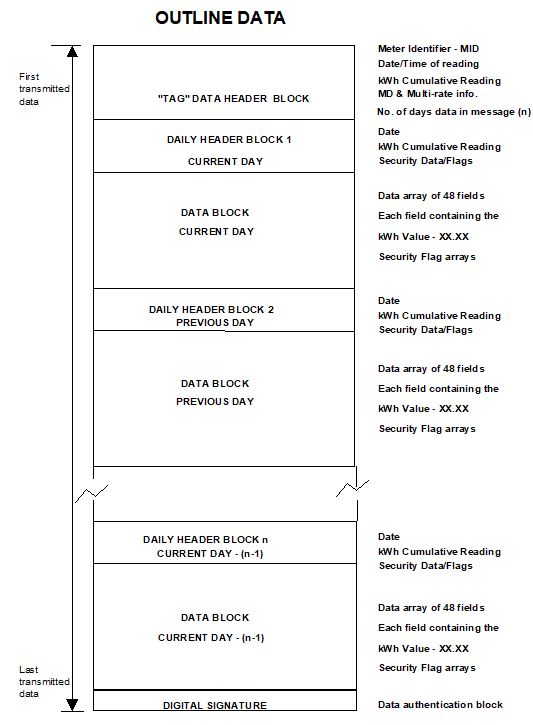
9.1 Appendix 1a: Outline Data Structure
The physical definition of the local optical data port is detailed in BS EN 61107. The general protocol specification is as detailed in BS EN 61107, augmented by the specifications contained herein.
The outline data structure described in Appendix 1a is expanded in Appendix 1b to provide more detail of the precise data structures and formats. Appendix 2a contains the data definitions and descriptions. Appendix 2b details the protocol examples to meet the functional requirements of the standard protocol. The data authentication process is outlined in Appendix 3.
The following guidelines have been established for local communications:
(i) The outstation transmits complete day information only, i.e. the current day's information is transmitted and "filled" where appropriate, if a period has not yet been completed. "Partial days" and "Missing days" must be "filled" in the data transmission from the outstation - see point (ii) below.
(ii) Chronological inconsistencies in the data block are not allowed. i.e. all data must be contiguous. "Partial days" or "Missing days" information, (due for example to power outages), must be "filled" in the data block that is transmitted by the outstation via its local communication port. Data shall be presented as if no Level 2 password access occurred during these periods and no consumption was recorded (i.e. the repetition of the last four digits of the kWh cumulative reading for the appropriate demand periods).
(iii) Data is transmitted in chronological order with current day's partial information transmitted first, oldest day's information transmitted last.
9.2 Appendix 1b: Data Structure and Formats
9.2.1 "TAG" Data Header Block
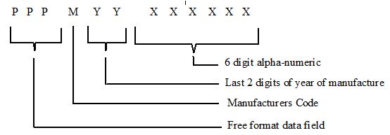
9.2.1.1 Meter Identifier-MID
Field | Character | Type | Range | Field Padding | Allowed Case |
PPP | P | Alpha-numeric | A-Z, 0-9 | Leading Zeroes | Upper or Lower Case |
M | M | Alpha | A-Z | - | Upper Case Only |
YY | Y | Numeric | 0-9 | - | - |
XXXXXX | X | Alpha-numeric | A-Z, 0-9 | Leading Zeroes | Upper Case Only |
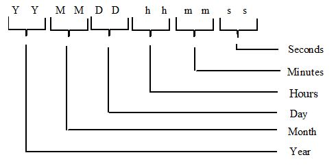
9.2.1.2 Date and Time of Reading of Meter (UTC)
9.2.1.3 kWh Cumulative Reading
The absolute value of the cumulative meter register at the time of the interrogation.
Expressed as :- 6 digit integer kWh value, padded with leading zeroes where appropriate.
1 | 2 | 3 | 4 | 5 | 6 |
Hundred Thousand | Ten Thousand | Thousands | Hundreds | Tens | Units |
9.2.1.4 Maximum Demands - MDs
MD register data block consisting of 6 digit (4 integer and two decimal places) kW values with an implied decimal place, padded with leading zeroes where appropriate.
(i) MD in kW in current charging period
(ii) MD in kW in previous charging period
(iii) Cumulative Maximum Demand
Register ID | 1000's | 100's | Tens | Units | 1/10ths | 1/100ths |
Current kW MD | 1 | 2 | 3 | 4 | 5 | 6 |
Previous kW MD | 1 | 2 | 3 | 4 | 5 | 6 |
Cumulative MD | 1 | 2 | 3 | 4 | 5 | 6 |
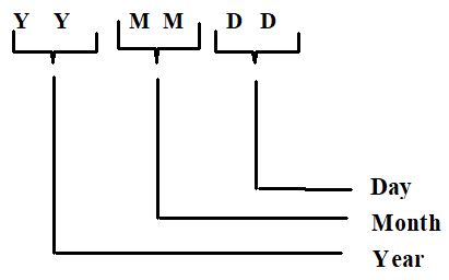
9.2.1.5 Date of Last MD Reset
Date of the last MD reset consisting of:-
9.2.1.6 Number of Maximum Demand Resets
The numerical value representing the last two digits of the number of Maximum Demand Resets, rollover to zero after value NN = 99.
9.2.1.7 Multi-rate Energy Registers
Multi-rate energy registers at time of data read out consisting of 6 digit integer kWh values, padded with leading zeroes where appropriate.
Register ID | 100k's | 10k's | 1000's | 100's | Tens | Units |
Rate 1 | 1 | 2 | 3 | 4 | 5 | 6 |
Rate 2 | 1 | 2 | 3 | 4 | 5 | 6 |
Rate 3 | 1 | 2 | 3 | 4 | 5 | 6 |
Rate 4 | 1 | 2 | 3 | 4 | 5 | 6 |
Rate 5 | 1 | 2 | 3 | 4 | 5 | 6 |
Rate 6 | 1 | 2 | 3 | 4 | 5 | 6 |
Rate 7 | 1 | 2 | 3 | 4 | 5 | 6 |
Rate 8 | 1 | 2 | 3 | 4 | 5 | 6 |
This data block should always be of the same size. All data items should be transmitted, even if never initialised or used e.g. MD register on single phase meter, 8 rate register block even if 4 rate single phase meter, or if rate currently inactive e.g. due to tariff change.
9.2.1.8 Number of Days Data in Message
The numerical value representing the number of days of data to be transmitted by the outstation in response to a request for a data output.
No. of days of data in message | N | N | N |
| | | |
Day identifier for the 24 hour period to which the 30 minute data relates.
9.2.2.2 Start of Day kWh Cumulative Reading
The absolute value of the cumulative meter (channel) register at 00:00 hours, at the start of the 24 hour period, to which the 48 periods of information relate.
Expressed as:- 8 digit kWh value, comprising 6 integers and 2 decimal digits with an implied decimal place, padded with leading zeroes where appropriate.
1 | 2 | 3 | 4 | 5 | 6 | 7 | 8 |
Hundred Thousand | Ten Thousand | Thousands | Hundreds | Tens | Units | Tenths | Hundredths |
9.2.2.3 Security Data and Flags
The normal status of each flag is logic zero and the presence or occurrence of an identified event is signalled by setting the flag to logic 1.
(i.) NNN - No. of successful level 2 accesses (maximum count = 7);
(ii.) BM - Battery Maintenance Flag;
(iii.) CF - Clock Failure;
(iv.) MD - MD reset flag, set for the day on which the MD was reset; and
(v.) PO - 24 hour continuous power outage of the outstation.
The security data and flags shall be coded into a single byte as follows:
Bit | 7 | 6 | 5 | 4 | 3 | 2 | 1 | 0 |
Type | - | PO | MD | CF | BM | N | N | N |
(Bit 7 is reserved for future use).
The truncated absolute value of the cumulative meter (channel) register at the end of the 30 minute period, to which the value relates. Expressed as :- 4 digit kWh value, comprising two integers and two decimal digits, with an implied decimal place.
1 | 2 | 3 | 4 |
Tens | Units | Tenths | Hundredths |
Appended for each 30 minute record are three security flags:
i) Reverse running indication;
ii) Successful level 2 password access; and
The normal status of these flags is logic zero and the presence or occurrence of an identified event is signalled by setting the flag to logic 1.
The data block will consist of a contiguous data array of 48, 4 digit values representing the value (truncated kWh cumulative register) for each respective demand period of the day e.g.
2220 2221 2222 2223 2224 2225 2226 2227
2228 2229 2230 2231 2232 2233 2234 2235
2236 2237 2238 2239 2240 2241 2242 2243
2244 2245 2246 2247 2248 2249 2250 2252
2252 2253 2254 2255 2256 2257 2258 2259
2260 2262 2262 2263 2264 2265 2266 2267
The data flags shall be presented as individual bit arrays with a flag for each demand period of the day in the array (48 bits per day). The sequence and location of individual bits within the data flag array corresponds directly to the demand period number of the respective 30 minute data value. i.e. bit 1 associated with demand period 1 (00:00 to 00:30) bit 48 associated with demand period 48 (23:30 to 24:00).
Data that has not yet been generated for the individual 30 minute demand periods i.e. in current day block for times following the time of data readout, shall be represented by FFFF. All flags for these associated periods shall be set to logic 0.
The data authenticator is automatically appended to the data at the end of reading out all the daily data records, resulting from a read ‘n’ days request. The data authenticator is detailed in Appendix 3.
10. Appendix 2a: Data Definitions and Descriptions
10.1.1 General Definition
Complete set of data for one communications session
Identifier ::= NamedVariableList
scope of access VDE-specific
list of named variables 8, 16, 24, 32, 40, 48, 56, 64, 72, 80, 88
10.2 Meter Identifier - MID
10.2.1 General Definition
12 characters representing the Meter Identifier - MID
Identifier ::= NamedVariableObject
scope of access VDE-specific
type description visible-string(SIZE(12))
read-write flag READ-ONLY
Identifier ::= NamedVariableObject
scope of access VDE-specific
type description visible-string(SIZE(12))
read-write flag READ-ONLY
10.3 Date and Time of Reading Meter
10.3.1 General Definition
12 characters representing the date and time
DateAndTime ::= NamedVariableObject
scope of access VDE-specific
type description numeric-string(SIZE(12))
read-write flag READ-ONLY
10.4 kWh Cumulative Reading
10.4.1 General Definition
6 characters representing the total cumulative kWh in kWh
CumulativekWh ::= NamedVariableObject
scope of access VDE-specific
type description numeric-string(SIZE(6))
read-write flag READ-ONLY
10.5 Current kW Maximum Demand
10.5.1 General Definition
6 characters representing the current kW MD in 1/100s of a kW.
CurrentkWMD ::= NamedVariableObject
scope of access VDE-specific
type description numeric-string(SIZE(6))
read-write flag READ-ONLY
10.6 Previous kW Maximum Demand
10.6.1 General Definition
6 characters representing the previous kW MD in 1/100s of a kW.
PreviouskWMD ::= NamedVariableObject
scope of access VDE-specific
type description numeric-string(SIZE(6))
read-write flag READ-ONLY
10.7 Cumulative Maximum Demand
10.7.1 General Definition
6 characters representing the cumulative MD in 1/100s of a kW.
CumulativeMD ::= NamedVariableObject
scope of access VDE-specific
type description numeric-string(SIZE(6))
read-write flag READ-ONLY
10.8 Date Of Last MD Reset
10.8.1 General Definition
6 characters representing the date of the last maximum demand reset.
MDResetDate :: = NamedVariableObject
scope of access VDE-specific
type description numeric-string(SIZE(6))
read-write flag READ-ONLY
10.9 Number Of Maximum Demand Resets
10.9.1 General Definition
2 characters representing the number of maximum demand resets, 00 - 99.
NumMaxDemandResets :: = NamedVariableObject
scope of access VDE-specific
type description numeric-string(SIZE(2))
read-write flag READ-ONLY
10.10 Multi-rate Energy Registers
10.10.1 General Definition
Eight registers containing the multi-rate kWh energy in kWh.
MultiRatekWh ::= NamedVariableObject
scope of access VDE-specific
type description compact-array(SIZE(8)) OF
read-write flag READ-ONLY
10.11 Number of Days Data in Message
10.11.1 General Definition
Three characters representing the number of days of data to be transmitted.
NumberOfDays ::= NamedVariableObject
scope of access VDE-specific
type description numeric-string(SIZE(3))
read-write flag READ-ONLY
10.12.1 General Definition
Daily data block comprising header data and profile data.
DailyData ::= NamedVariableObject
scope of access VDE-specific
type description array OF DailyDataType SIZE(N)
read-write flag READ-ONLY
Where N = 20, 100, 250 or 450
DailyDataType :: = structure
DayIdentifier numeric-string(SIZE(6))
StartCumulativekWh numeric-string(SIZE(8))
DailyFlags bit-string(SIZE(8))
HalfHourData compact-array(SIZE(48)) OF
ReverseRunning bit-string(SIZE(48))
Level2 bit-string(SIZE(48))
PowerFail bit-string(SIZE(48))
10.13.1 General Definition
Eight byte string calculated using an authentication algorithm, an internal 8 byte authentication key and the preceding data.
Authenticator ::= NamedVariableObject
scope of access VDE-specific
type description octet-string(SIZE(8))
read-write flag READ-ONLY
10.14.1 General Definition
Eight byte string used by the authentication algorithm when calculating the authenticator.
AuthenticationKey ::= NamedVariableObject
scope of access VAA-specific
VAA name 39 -- VAAManagement
type description octet-string(SIZE(8))
read-write flag WRITE-ONLY
10.15.1 General Definition
Six character string consisting of case sensitive alpha characters (A to Z), digits (0 to 9) or the underscore character (_).
Level2Password ::= NamedVariableObject
scope of access VAA-specific
VAA name 39 -- VAAManagement
type description visible-string(SIZE(6))
read-write flag WRITE-ONLY
10.16.1 General Definition
12 characters representing the date and time
DateAndTimeSet ::= NamedVariableObject
scope of access VAA-specific
VAA name 39 -- VAAManagement
type description numeric-string(SIZE(12))
read-write flag READ-WRITE
10.17.1 General Definition
Signed integer representing the number of seconds by which to adjust the time. The maximum permissible value is ± 900 seconds.
DateAndTimeSet ::= NamedVariableObject
scope of access VAA-specific
VAA name 39 -- VAAManagement
type description integer16
read-write flag WRITE-ONLY
10.18 Maximum Demand Reset
10.18.1 General Definition
Boolean which when written to will initiate a maximum demand reset.
MDReset ::= NamedVariableObject
scope of access VAA-specific
VAA name 39 -- VAAManagement
type description integer8
read-write flag WRITE-ONLY
10.19 Free Format Field of Meter ID
10.19.1 General Definition
3 characters representing the free format field section of the Meter Identifier.
Identifier ::= NamedVariableObject
scope of access VAA-specific
VAA name 39 -- VAAManagement
type description visible-string(SIZE(3))
read-write flag READ-WRITE
10.20 Code of Practice Six Identifier
10.20.1 General Definition
An eleven character string identifying the issue number of Code of Practice Six.
Writing to this variable will invoke manufacturer specific features.
Identifier ::= NamedVariableObject
scope of access VAA-specific
VAA name 39 -- VAAManagement
type description visible-string(SIZE(11))
read-write flag READ-WRITE
11. Appendix 2b: Transport Protocol and Examples
This appendix defines how the BS EN 61107 protocol is used to transfer the DLMS named variables and named variable list specified in Appendix 2a.
This appendix also defines how the data within each named variable is encoded into a sequence of bytes according to the DLMS definitions, ASN.1 type definitions and the A-XDR encoding rule.
Some of the named variables in appendix 2a are not individually readable, but are readable via the data block named variable list. This appendix identifies which named variables are readable.
This section defines how the read, write and password commands of BS EN 61107 mode C are used to access named variables.
11.2.1 Read Selected Meters
This is implemented via the multi-drop option of BS EN 61107. Where more than one meter is connected to the same serial port it is necessary to include a device identifier in the initial sign-on string.
/?<Optional device identifier>!<CR><LF>
The device identifier can be up to 16 characters.
To achieve level 2 security an BS EN 61107 P1 command must be sent to the meter. The P1 command should contain the 6 character password.
<SOH> P 1 <STX> ( 123456 ) <ETX> <BCC>
for a password of “123456”.
Spaces in the above example are purely to aid readability and are not transmitted.
For reads of the named variables a BS EN 61107 read command will be used. The partial block command type R3 will be used to read named variable zero (Data Block). Command type R1 will be used for all other reads.
To avoid conflicts with manufacturer specific addresses (used for communications outside the scope of this Code of Practice), each manufacturer will implement a method of switching to manufacturer specific operation, whereby the same address may be used for other purposes.
The method for switching to manufacturer specific operation is to write to the ‘Code of Practice Six Identifier’ named variable 65528. The meter must return to supporting the functionality and addresses specified in this document following a BS EN 61107 sign on.
The address field within the read commands will be used to hold the variable name. This variable name is passed as a 4 digit hex number, e.g. password = 112, has the hex address of 0070.
The length field within the read commands will be unused and set to zero, except when reading the data block named variable.
When reading the data block named variable the length field of the read request identifies the number of days worth of data to return. If the number of days requested exceeds the quantity of days stored in the meter then the meter returns all of the days data it has stored. This provides a mechanism for reading all the available days data in the meter. Reading zero days worth of data shall result in the meter returning the authenticated tag data header block only, including a zero in the tag data header field “Number of days data in message”.
Below is a summary of the named variables available for reading directly, their variable name, and whether level 2 security is needed to access them.
Variable | Name | Access commands | level 2 security ? |
Data Block | 0 | R3 | no |
Authentication Key | 104 | W1 | yes |
Password | 112 | W1 | yes |
Date and Time Set | 120 | R1, W1 | yes for W1 |
Time Adjust | 128 | W1 | yes |
Maximum Demand Reset | 136 | W1 | yes |
Free format field of Meter ID (PPP) | 144 | R1,W1 | yes |
Meter Identifier | 152 | R1 | no |
COP6 Identifier | 65528 | R1, W1 | no/no |
Write to named variables shall be performed using the BS EN 61107 W1 command. As for the read command the address field of the command is used to pass the variable name.
All writes to the meter, except writes to the Code of Practice Six Identifier, require level 2 security as defined in the table above.
Writes to the Code of Practice Six Identifier do not modify data at this level but invoke manufacturer specific addressing modes.
The read command to fetch the data block variable is as follows :-
<SOH> R3 <STX> 0000 ( nnnn ) <ETX> <BCC>
where nnnn has values zero to FFFF hex identifying the number of days worth of data required including the current day. nnnn is expressed as a 4 digit hex number.
The data will be passed back to the meter in many BS EN 61107 data messages, using partial block transfer. Each block does NOT necessarily relate to a specific day.
The address field in the data messages used to transfer the data shall be zero for the first message and increment for each following message.
The data is transmitted with the most recent data first.
All data specified in Appendix 1 except the half hour data flags, shall be transmitted unchanged since it contains only printable ASCII characters which can be transmitted using BS EN61107 The half hour data flags specified in Appendix 1, shall be converted to ASCII hex character pairs before transmission, with the most significant nibble first.
The half hour data flags which consist of arrays of 48 bit flags are transmitted as a sequence of 12 ASCII hexadecimal characters, where the first hex character transmitted holds the bit flags for the first four integration periods in the day, and within each hex character the most significant bit represents the earliest bit flag and the least significant bit represents the latest bit flag. Hence the bit flag for 00:00 to 00:30 is transmitted in the most significant bit of the first hexadecimal character transmitted, and the bit flag for 23:30 to 24:00 is transmitted in the least significant bit of the twelfth character.
The response to the BS EN61107 read command is a sequence of data messages as follows:-
<STX>0000(meter identifier……..)<EOT><BCC>
<STX>0001(……………………...)<EOT><BCC>
<STX>xxxx(……………………...)<ETX><BCC>
The format of the data transferred is described below. Before each set of data characters is an explanation of the data source.
Text in italics represent fields to be replaced by data values. Only these fields are transmitted, the (DLMS packaging) characters in normal text are not transmitted. The format of the fields is as defined in Appendix 1 unless stated otherwise.
Read named variable list zero is returning
Variable read request successful 00
Data type = visible-string 0A
Identifier meter identifier (12 characters)
Variable read request successful 00
Data type = visible-string 0A
DateAndTime of reading date and time of reading (12 characters)
Variable read request successful 00
Data type = visible-string 0A
CumulativekWh cumulative kWh (6 characters)
Variable read request successful 00
Data type = visible-string 0A
CurrentkWMD current kW maximum demand (6 characters)
Variable read request successful 00
Data type = visible-string 0A
PreviouskWMD previous kW maximum demand (6 characters)
Variable read request successful 00
Data type = visible-string 0A
CumulativeMD cumulative maximum demand (6 characters)
Variable read request successful 00
Data type = visible-string 0A
MDResetDate date of last MD reset (6 characters)
Variable read request successful 00
Data type = visible-string 0A
NumMaxDemandResets number of MD resets (2 characters)
Variable read request successful 00
Data type = compact-array 13
Array element type - visible-string 0A
MultiRatekWh eight rate kWh registers (48 characters = 8x6)
Variable read request successful 00
Data type = visible-string 0A
NumberOfDays number of days worth of data (3 characters)
Variable read request successful 00
Number of elements of array number of days worth of data expressed as a 4
digit ASCII hex number (zero upwards).
Then the following is repeated for each days worth of data :-
Number of items in structure 07
Data type = visible string 0A
DayIdentifier day identifier YYMMDD (6 characters)
Data type = visible string 0A
StartCumulativeDWh start of day cumulative DWh (8 characters)
Data type = Bit string 04
DailyFlags daily security data and flags expressed as a
two digit ASCII hex number.
Data type = compact array 13
Array element type = visible string 0A
HalfHourData forty eight truncated cumulative energy
register values of four characters each
ReverseRunning forty eight reverse running bit flags expressed
as a twelve digit ASCII hex number
Level2 forty eight level 2 access bit flags expressed as
a twelve digit ASCII hex number
PowerFail forty eight power failure bit flags expressed as
a twelve digit ASCII hex number
Variable read request successful 00
Data type = visible string 0A
Authenticator authenticator expressed as a sixteen digit ASCII hex number
The purpose of the authenticator is to verify the origin and authenticity of data retrieved from the meter.
An Authenticator is automatically provided at the end of the sequence of reading ‘n’ days meter reading records. On receipt of the request to read ‘n’ days records, the data authenticator seed is automatically reset (set to 0) by the meter. Once the last day’s data has been transmitted, the resultant authenticator is then transmitted.
No direct access is provided for writing the seed or reading the authenticator.
A description of how the authenticator is calculated is defined in Appendix 3.
Assuming level 2 access has been granted, the level authentication key is set by writing to variable 104 as defined in Appendix 2a.
The authentication key is defined as an eight byte binary number which is transferred as a sixteen character ASCII HEX value
e.g. To set the authentication key to 0123456789ABCDEF hexadecimal
To meter <SOH> W 1 <STX> 0068 ( 0123456789ABCDEF )<ETX><BCC>
Assuming level 2 access has been granted, the level 2 password is set by writing to variable 112 as defined in Appendix 2a.
e.g. To set the password to “ABC123”
To meter <SOH> W 1 <STX> 0070 ( ABC123 ) <ETX> <BCC>
Assuming level 2 access has been granted, the date and time is set by writing to variable 120 as defined in Appendix 2a.
e.g. To set the date and time to 18 December 1995 09:25:00
To meter <SOH>W1<STX>0078(951218092500)<ETX><BCC>
To read the date and time, Level 2 access is not required and it can be retrieved by reading named variable 120.
To meter <SOH>R1<STX>0078(0)<ETX><BCC>
From meter <STX>0078(951218092500)<ETX><BCC>
Where the date and time is 18th December 1995 at 09:25:00.
The time in the meter can be adjusted by a specified number of seconds by writing to variable 128 as defined in Appendix 2a. This method of clock synchronisation must never introduce or skip integration periods, i.e. it must guarantee that there are always 48 integration periods in a day.
The data passed in the write command represents the number of seconds to advance or retard the meters clock by and is a signed integer of length two bytes which is encoded as a four character ASCII HEX number.
e.g. To advance the clock by 12 seconds
To meter <SOH> W1 <STX> 0080 ( 000C ) <ETX> <BCC>
e.g. To retard the clock by 12 seconds
To meter <SOH> W1 <STX> 0080 ( FFF4 ) <ETX> <BCC>
Where 0xFFF4 is the two’s complement of 0x000C.
Assuming level 2 access has been granted, a maximum demand reset can be initiated by writing one character (any value) to variable 136 as defined in Appendix 2a.
To meter <SOH> W1 <STX> 0088 ( 0 ) <ETX> <BCC>
11.10 Free Format Field of Meter ID (ppp)
Assuming Level 2 access has been granted, the free format part of the meter ID can be written to by writing to a named variable 144 as defined in Appendix 2a.
e.g. To set the value “ABC”
To meter <SOH>W1<STX>008C(ABC)<ETX><BCC>
11.11 Code of Practice Six Identifier
Named variable 65528 can be read to determine the Issue of Code of Practice Six supported by the meter. The format of the response is fixed as “COP6I300^^^”, where “^” represents a space character and “I300” represents Issue 3.00 of Code of Practice Six.
To meter <SOH>R1<STX>FFF8(0)<ETX><BCC>
From meter <STX>FFF8(COP6I300^^^)<ETX><BCC>
Writing to this address invokes manufacturer specific addressing modes.
12. Appendix 3: Authentication
12.1 Authentication Overview
The purpose of authentication is to ensure that the receiver of the information can be confident that the contents of the message have not been altered since it left the sender and that the identity of the sender is not misrepresented.
The data authentication process uses a system whereby an Authentication Key will be loaded into Outstations by authorised parties. This Authentication Key will then be used to form an Authenticator on all the data to be communicated. The same Authentication Key will be provided to the authenticating parties. This will ensure that all authorised holders of the Authentication Key will be able to validate the authenticity of the information being transferred, provided of course that they also have knowledge of the Authentication Algorithm and its method of use.
The Authentication Key programmed into outstations and other validation equipment can be changed should the authentication system be compromised by disclosure or discovery of the key.
A Key Management System is required to ensure secure creation, storage and distribution of the Authentication Key to all parties concerned. This system is outside the scope of this document.
Different Authentication Keys may be used for various Outstations or groups of Outstations if required. However, this will require a more complex Key Management System to be used, and knowledge of a number of Authentication Keys from which the appropriate one must be selected, by the authenticating party.
12.2 Authentication Process
The complete Data Block described in Appendix 1(a) will be signed by an Authenticator to provide authentication of the source and validation of the data. This allows the content of the message to be sent in plain text and still to be validated and authenticated by authorised parties only.
There are four elements used in the calculation of the Authenticator. These are:
a) The Authentication Key
b) The Authentication Algorithm,
d) The method by which (a) and (b) above operate on the contents of the Data Block to create the Authenticator.
The Authentication Key is an 8 byte binary number (56 bits of key data and 8 bits of parity) that is kept secret. It is placed only in those devices that need either to generate an Authenticator, or to check that the Authenticator received is valid.
The Algorithm used in the calculation of the Authenticator is the Data Encryption Standard (DES). This is a publicly available secret key block encryption algorithm, detailed in the following Standard: ANSI X3.92-1981.
The Data Block for authentication is detailed in Appendix 1(a). All the data in the total Data Block, consisting of the data in the Tag Header Block and the data for each of the days of daily data transmitted, are included in the Authenticator calculation. A change to any item of data in the Data Block affects the Authenticator.
The method by which the Authenticator is calculated, (using the Authentication Key, DES, and the data in the Data Block) is detailed in a controlled document, available on request to authorised parties from the BSCCo. However, the security of Authentication depends essentially on the security of the key, not on the security of the controlled document.
13. Appendix 4: Authenticator Calculation
This Appendix 4: Authenticator Calculation is a controlled document, available on request to authorised parties from the BSCCo (Elexon Limited).
14. Appendix 5: Multi-rate Register Switching Regime
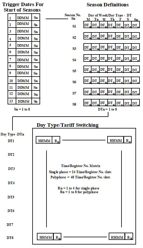
Multi-rate registers shall be programmable to provide the following minimum seasonal time of use tariff switching regime as described below and in the following diagrams;
A minimum of 24 stored register switching times for a single phase and 48 for polyphase Meter systems at any one time.
A minimum of 8 day types, each of which has an individual set of register switching times.
A sequential day of the week number to allow register switching to take place on any day of the week or combinations of days of the week. Monday shall be day 1.
A minimum of 8 seasons. Different weekday or combinations of weekdays register switching time registers can apply to each season.
In addition to switching times a minimum of 13 MD Reset dates, commencing at the start of the settlement day, for the start of the seasons.
A minimum of 2 daylight clock time changes, indicated by date and month during which a time offset of 0, 1 or 2 hours shall be implemented for the purposes of the tariff switching regime only, i.e. this shall not affect the UTC clock. The offset is specified with respect to UTC and shall be actioned at 02.00 hours UTC on the date(s) specified.
A minimum of 12 exclusion dates during which any day’s register switching times, indicated by day type, can be implemented for each exclusion date.
Where Maximum Demand (MD) metering is being operated the MD shall be programmable to reset automatically as defined by 13 MD reset dates.
Where load switching is provided it shall comply with the appropriate standards.
Exclusion Dates | | Date of MD Reset |
1 | DDMM | DT | | 1 | DDMM |
2 | DDMM | DT | | 2 | DDMM |
3 | DDMM | DT | | 3 | DDMM |
4 | DDMM | DT | | 4 | DDMM |
5 | DDMM | DT | | 5 | DDMM |
6 | DDMM | DT | | 6 | DDMM |
7 | DDMM | DT | | 7 | DDMM |
8 | DDMM | DT | | 8 | DDMM |
9 | DDMM | DT | | 9 | DDMM |
10 | DDMM | DT | | 10 | DDMM |
11 | DDMM | DT | | 11 | DDMM |
12 | DDMM | DT | | 12 | DDMM |
| | | | 13 | DDMM |
Daylight Saving Clock Changes
DDMM | H | Set Tariff clock at 02.00 hours UTC to UTC plus offset ‘H’ hours on date specified |
| | Notes: - Valid range of ‘H’ is either 0, 1 or 2. - Two daylight saving changes are required. |
| | |
15. Annex: Use of Code of Practice Six in CVA Settlements
CVA Meter Operators may choose in the CVA Settlements (i.e.>100kW) to use CoP 6 for multi feeder sites where one or more of the feeders is whole current. If CVA MOAs choose this option for whole current feeders the following instructions must be observed. These instructions will continue to apply to sites continuing to trade in CVA Settlements beyond 1998 but not sites trading in SVA Settlements.
Section numbering refers to this issue of Code of Practice Six. For the avoidance of doubt, these instructions should replace the requirements of the wording for equivalent numbered paragraphs in their entirety.
The Outstation shall be set to the Universal Time Clock (UTC). No switching between UTC and British Summer Time shall occur for settlement data storage requirements.
Time synchronisation of the Outstation shall be maintained within +/- 20 seconds of UTC. This may be performed remotely by the Settlement Instation as part of the normal on going interrogation process or locally by an Interrogation unit.
Facilities for routine time synchronisation using 30 minute synchronising pulses or broadcast clock should not be used.
The clock of the Outstation shall be capable of being set or adjusted using the local or remote communications port but only once during the demand period.
The overall limits of error for time keeping allowing for a failure to communicate with the Outstation for an extended period of 20 days shall be:
a) the completion of each Demand Period shall be at a time which is within +/- 20 seconds of UTC; and
b) the duration of each Demand Period shall be within +/- 0.6% except where time synchronisation has occurred in a Demand Period.
6.4.2 Remote Interrogation
An interrogation facility shall be provided for remote interrogation and it shall not be possible to disconnect this link at the Outstation without the breaking of a Settlement seal.
Any port for connection to external data communication equipment shall be compatible with CCITT V24 and CCITT V28.
Error checking facilities shall be provided between the Outstation and the Settlement Instation.
The data shall be to the standard data structure as set out in Appendix 1b. The protocol shall be approved by the Panel.
The media (i.e. PSTN, Paknet, etc.) for remote interrogation shall be approved by the Panel.
1) CVA MOAs or other parties proposing the use of Code of Practice Six meters in the CVA Settlements are liable for the costs of developing modifications to the Settlement Instation to ensure compatibility. Such modifications will have to be procured before approval of the protocol can be given.
2) Attention is drawn to section 2 of Code of Practice Six that clearly states that if Reactive Energy measurement is required then Code of Practice Five metering shall be used.