Advanced Search

Code of Practice 7: The Metering of Energy Imports via Low Voltage Circuits Fused at 100 AMPS or Less per Phase for Settlement Purposes

v 7.0
Download

Balancing and Settlement Code

Code of Practice Seven

CODE OF PRACTICE FOR THE METERING OF ENERGY IMPORTS VIA LOW VOLTAGE CIRCUITS FUSED AT 100 AMPS OR LESS PER PHASE FOR SETTLEMENT PURPOSES

Issue 2

Version 7.0

Date: 1 September 2021

Code of Practice Seven

CODE OF PRACTICE FOR THE METERING OF ENERGY IMPORTS VIA LOW VOLTAGE CIRCUITS FUSED AT 100 AMPS OR LESS PER PHASE FOR SETTLEMENT PURPOSES.

1. Reference is made to the Balancing and Settlement Code for the Electricity Industry in Great Britain and, in particular, to the definition of “Code of Practice” in Annex X-1 thereof.

2. This is Code of Practice Seven Issue 2, Version 7.0

3. This Code of Practice shall apply to Metering Systems comprising Metering Equipment that are subject to the requirements of Section L of the Balancing and Settlement Code.

4. This Code of Practice is effective from 1 September 2021

5 This Code of Practice has been approved by the Panel.

Intellectual Property Rights, Copyright and Disclaimer

The copyright and other intellectual property rights in this document are vested in Elexon or appear with the consent of the copyright owner. These materials are made available for you for the purposes of your participation in the electricity industry. If you have an interest in the electricity industry, you may view, download, copy, distribute, modify, transmit, publish, sell or create derivative works (in whatever format) from this document or in other cases use for personal academic or other non-commercial purposes. All copyright and other proprietary notices contained in the document must be retained on any copy you make.

All other rights of the copyright owner not expressly dealt with above are reserved.

No representation, warranty or guarantee is made that the information in this document is accurate or complete. While care is taken in the collection and provision of this information, Elexon Limited shall not be liable for any errors, omissions, misstatements or mistakes in any information or damages resulting from the use of this information or action taken in reliance on it.

AMENDMENT RECORD

ISSUE

DATE

VERSION

CHANGES

AUTHOR

APPROVED

1

08/02/96

v 3.00

Approved by PEC

1998 MTF

PEC, 15/02/96

2

18/11/96

v 3.10

Approved by MDC

MDC

MDC

2

Code Effective Date1

v 3.10

Re-badging of Code of Practice Seven for the implementation of the Balancing and Settlement Code

BSCCo

Panel 16/11/00

(Paper 07/003)

2

BETTA Effective Date

v4.0

BETTA 6.3 and CP669 for the SVA February 2005 Release

BSCCo

SVG/48/004

2

25/06/09

5.0

CP1264 for the June 09 Release

BSCCo

ISG94/01

SVG94/02

2

26/11/09

6.0

Modification P230

BSCCo

Panel

2

01/09/21

7.0

P420 – 1 September 2021 Non-Standard Release

BSCCo

Panel 316/05

CODE OF PRACTICE FOR THE METERING OF ENERGY IMPORTS VIA LOW VOLTAGE CIRCUITS FUSED AT 100 AMPS OR LESS PER PHASE FOR SETTLEMENT PURPOSES.

1. FOREWORD

This Code of Practice defines the minimum requirements for a Metering and Data Collection System (MDCS) required for the recording of electricity transfers at points of connection and/or supply VIA LOW VOLTAGE CIRCUITS FUSED AT 100 AMPS OR LESS PER PHASE.

The Panel shall retain copies of, inter alia, the Code of Practice together with copies of all documents referred to in them, in accordance with the provisions of the Balancing and Settlement Code (“Code”).

2. SCOPE

This Code of Practice states the practices that shall be employed, and the facilities that shall be provided for the measurement, recording and collection of the quantities required for Settlement purposes.

This Code of Practice specifically applies to Metering and Data Collection Systems (MDCS) to be installed FOR THE METERING OF ENERGY IMPORTS VIA LOW VOLTAGE CIRCUITS FUSED AT 100 AMPS OR LESS PER PHASE.

Reactive energy measurement is not covered within this Code of Practice, where kVA and/or kvar is required Code of Practice Five equipment shall be used.

It will be noted that this Code of Practice and Code of Practice Six apply to the same circuit consumption. For clarity, the distinction is that Code of Practice Six sets out the requirements for a Settlement Metering Equipment and Code of Practice Seven specifies the settlement requirements as part of a wider metering and data collection infrastructure providing data to the Data Processing interface. Code of Practice Seven does not require Code of Practice Six Meters to be used. It would, however, be possible to construct a Code of Practice Seven system using Code of Practice Six Metering.

It derives force from the metering provisions (Section L) of the Balancing and Settlement Code, to which reference should be made. It should also be read in conjunction with the relevant BSC Procedures for, inter alia, operation of the data collection systems.

Metering Equipment that meets the requirements of this Code of Practice is also applicable where the Registrant is required by its Supply Licence (and as referenced in Section L3.2.6) to install Metering Equipment that is capable of providing measured electricity consumption data for multiple periods (at least half hourly) and providing the Registrant with remote access to such data.

This Code of Practice does not contain the calibration, testing and commissioning requirements for Metering Equipment used for Settlement purposes. These requirements are detailed in Code of Practice Four - “Code of Practice for Calibration, Testing and Commissioning Requirements for Metering Equipment for Settlement Purposes”.

Dispensations from the requirements of this Code of Practice may be sought in accordance with the Code and the BSCP32.

In the event of an inconsistency between the provisions of this Code of Practice and the Code, the provisions of the Code shall prevail.

3. REFERENCES

The following documents are referred to in the text:-

BS EN 61036 AC Static Watt-hour Meters for Active Energy (Classes 1 and 2).

BS EN 60521 Specification of Class 0.5, 1 and 2 Single-Phase and polyphase, single rate and Multi rate Watt hour meters.

IEC 1334-4-41 Application Protocols: Distribution Line Message Specification.

SI 792 The Meters (Certification) Regulations 1990.

Electricity Act 1989 Schedule 7, as amended by the schedule 1, to the Competition and Services (Utilities) Act 1992.

BS EN 7799 Code of Practice for Information Security Management.

Balancing and Settlement Code Section X; Annex X-1 and Section L and BSC Procedures.

Code of Practice Four Code of Practice for Calibration, Testing and Commissioning Requirements for Metering Equipment for Settlement Purposes.

Code of Practice Five Code of Practice for the Metering of Energy Transfers with a Maximum Demand of up to (and Including) 1MW Covered by the Balancing and Settlement Code.

Code of Practice Six Code of Practice for Metering of Energy Imports via Low Voltage Circuits Fused at 100Amps or Less per Phase for Settlement Purposes.

4. DEFINITIONS AND INTERPRETATIONS

Save as otherwise expressly provided herein, words and expressions used in this Code of Practice shall have the meanings attributed to them in the Code and are included for the purpose of clarification.

Note: * indicates definitions in the Code.

Note: † indicates definitions which supplement or complement those in the Code.

Note: ‡ indicates definitions specific to this Code of Practice

4.1 Active Energy *

Active Energy means the electrical energy produced, flowing or supplied by an electrical circuit during a time interval, and being the integral with respect to time of the instantaneous Active Power measured in units of watt-hours or standard multiples thereof;

4.2 Active Power *

Active Power means the product of voltage and the in-phase component of alternating current measured in units of watts and standard multiples thereof, that is;

1,000 Watts = 1 kW

1,000 kW = 1 MW

4.3 Demand Period ‡

Demand Period means the period over which Active Power is integrated to produce Demand Values. Each Demand Period shall be of 30 minutes duration, one of which shall finish at 24:00 hours.

4.4 Demand Values ‡

Demand Values means, expressed in kW twice the value of kWh recorded during any Demand Period. The Demand Values are half hour demands and these are identified by the time of the end of the Demand Period.

4.5 Electricity *

"electricity" means Active Energy and Reactive Energy.

4.6 Energy Storage Device ‡

A device to provide standby power to the Metering Equipment clock and calendar in the event of Mains failure e.g. battery or supercapacitor.

4.7 Full Load ‡

Full Load means the product of the number of phases, maximum current (Imax), and rated voltage of the Meter at unity power factor.

4.8 Import

Import means, for the purposes of this Code of Practice, an electricity flow as specified within the Code.

4.9 Maximum Demand †

Maximum Demand expressed in kW means twice the greatest number of kWh recorded during any Demand Period.

4.10 Meter *

Means a device for measuring Active Energy and/or Reactive Energy.

4.11 Metering Clock ‡

Metering clock means a clock or system used for assigning a metered value to a specific Demand Period .

4.12 Metering Equipment *

Metering Equipment means Meters, measurement transformers (both voltage, current or combination units), metering protection equipment including alarms, circuitry, associated Communications Equipment and Outstation and wiring.

4.13 Meter Register ‡

Meter Register means a device, normally associated with a Meter, from which it is possible to obtain a reading of the amount of Active Energy that has been supplied by a circuit.

4.14 Metering and Data Collection System (MDCS) ‡

This MDCS means all components of equipment, including Metering Equipment, between the point of supply and or connection and the Data Processing Interface used in order to satisfy the requirements of Code of Practice Seven.

4.15 Data Processing Interface ‡

Data Processing Interface means a computer based system receiving data on a routine basis from selected MDCS on behalf of Suppliers or by their Agents.

4.16 Registrant *

Registrant means, in relation to a Metering System, the person for the time being registered in CMRS or (as the case may be) SMRS in respect of that Metering System pursuant to Section K of the Balancing and Settlement Code.

4.17 SVA Customer

SVA Customer means a person to whom electrical power is provided, whether or not that person is the provider of that electrical power; and where that electrical power is measured by a SVA Metering System.

4.18 UTC *

UTC means Co-ordinated Universal Time which bears the same meaning as in the document Standard Frequency and Time Signal Emission, International Telecommunication Union - RTF.460(ISBN92-61-05311-4) (colloquially referred to as Rugby Time).

5. Electrical Interface Requirements

5.1 Measured Quantities

For each circuit the following energy measurements are required for Settlement purposes:

(i) Import kWh.

5.2 Accuracy Requirements

The overall accuracy of the energy measurements shall at all times be within the limits of error specified in SI 792 Regulation 8 pertaining to Schedule 7 of the Electricity Act 1989.

Meters where certified shall be certified as set out in accordance with schedule 7 of the Electricity Act 1989.

Appropriate evidence to substantiate that these overall accuracy requirements are met shall be available for inspection to Panel or their agent(s).

5.3 Meters

For each circuit direct connected Active Energy Meters shall be used, which shall be in accordance with Schedule 7 of the Electricity Act 1989.

5.3.1 New Meters

New Meters shall comply with the requirements of either BS EN 61036 Class 2, for Indoor Meters or BS EN60521 Class 2. The rating for single phase Meters shall be 230 volts, 50Hz, 20 Amps basic or less and 100 Amps maximum and for polyphase Meters 230/400 volts, 50Hz, 40 Amps basic or less and 100 Amps maximum.

5.3.2 Existing Meters

Existing Meters may be used provided they were manufactured to the relevant British Standards. Ratings different to those quoted for new Meters may be utilised provided they are appropriate for the supply being metered.

5.4 Metering Equipment

All MDCS Metering Equipment (including Energy Storage Device) shall have a minimum design service life, without maintenance, of 10 years from date of manufacture.

Where separate items of equipment are provided they shall be individually protected against electrical overload.

Where Metering Equipment has a primary battery to provide back-up for the clock and calendar, this battery shall have a minimum standby service life of 3 years from the date of manufacture of the Metering Equipment i.e. supporting the clock for 3 years without mains power.

Where Energy Storage Devices other than primary batteries are used, the clock and calendar shall be supported for a period of 7 days without an external supply connected to cater for extended supply failure.

6. Supplier Interface Requirements

6.1 Displays and Facilities at a Site.

This section sets out the displays that shall be provided at the customers site. If such facilities are provided remote from the Meter the displays shall be updated on demand by the customer or at least once in any 24hr period.

The MDCS shall display as a minimum the following information:

    • total Import cumulative kWh per circuit, 6 digit integer kWh value padded with leading zeroes where appropriate for polyphase and 5 digit integer kWh value padded with leading zeroes where appropriate for single phase Meters.

The MDCS shall store the following data for each Meter such that it can be readily displayed if required by the Supplier. If this data is displayed it shall be made readily available to the Supplier (see Section 7):

(i) For Polyphase Meters:

    • Maximum Demand (“MD”) 6 digit (4 integer and 2 decimal places) kW value padded with leading zeroes where appropriate for the current and historic programmable charging period, e.g. monthly or statistical review period;

    • cumulative MD, 6 digit (4 integer and 2 decimal places) kW value padded with leading zeroes where appropriate;

    • number of MD resets (up to 99);

    • multi-rate display sequence as specified by the Supplier, with a minimum of 8 Registers selectable over the calendar year; and

    • current UTC or clock time and date as specified by the Supplier.

(ii) For single phase Meters:

    • multi-rate display sequence as specified by Supplier, with a minimum of 4 Registers selectable over the calendar year; and

    • current UTC or clock time and date as specified by the Supplier.

Further details on the multi rate register switching scheme are given in Appendix 4.

Where a multi-rate display sequence is enabled associated with a Meter, the default display shall be the cumulative kWh register of the active rate and the rate identifier. The initial operation of the display selector, if fitted, shall display the test display and the next operation shall display the total Import cumulative kWh. Subsequent operation of the display selector shall display register values in a sequence specified by the Supplier.

7. Requirements for the Data Processing Interface

The MDCS and its operator shall comply with BS7799 particularly sections 6,7,8, and 9.

7.1 Data Provision requirements

For each Meter, one Data Collection Agency shall be responsible for data collection.

The MDCS shall provide information in the formats specified in Appendix 1A, 1B and 2A. Open electronic data interchange standards shall be used.

7.1.1 Data Requirements

Data at the Data Processing Interface shall be provided for each Meter as follows and is further defined in Appendix 1:

(i) For each data exchange of the MDCS with Data Processing and for each metered data stream:

    • kWh cumulative total Meter Register value for each Meter to 6 digit integer kWh value padded with leading zeroes where appropriate (see section 7.7 on the conversion algorithm);

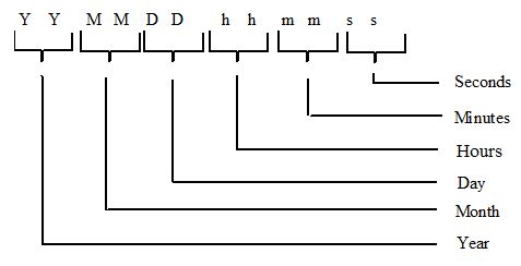
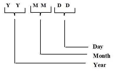
    • The date and time of the recording of the cumulative register reading [YYMMDDhhmmss];

    • The Meter identifier; 12 characters alphanumeric as defined in Appendix 1b,

    • For polyphase metering, Maximum Demand (MD), 6 digit (4 integer and 2 decimal places) kW value padded with leading zeroes where appropriate, for the current and previous programmable charging period e.g. monthly statistical review period as specified by the Supplier;

    • multi-rate cumulative Active Energy registers as specified by Supplier;

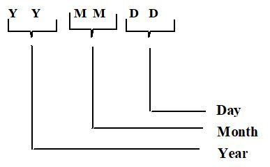
    • date of last MD reset if appropriate [YYMMDD]; and

    • number of days data returned from Meter.

(ii) The MDCS shall provide the following data for each Day or partial Day where available, for each metered data stream:

    • kWh cumulative total register value for each Meter to 8 digit (including 2 decimal place) kWh value padded with leading zeroes where appropriate

    • Where a battery is fitted supporting a Metering Clock, a battery change maintenance flag shall be provided based on the standby battery service life;

    • An indication should a Metering Clock failure occur;

    • the number of successful password accesses (i.e. any access that changes static or dynamic data) made on that day to a maximum of 7;

    • MD reset flag as appropriate;

    • The Settlement Day Date [YYMMDD]; and

    • A flag to indicate any power outage for the whole of a Settlement Day.

(iii) For each Demand Period the MDCS shall provide, for each metered data stream:

    • A flag to indicate if net reverse energy flow has taken place;

    • Truncated absolute cumulative Meter Register reading in the range 10’s of kWh, kWh, 1/10 kWh and 1/100 kWh;

    • A flag to indicate successful password access (i.e. any access that changes static or dynamic data); and

    • A flag to indicate that any power outage has occurred.

Where billing information is displayed in accordance with section 6.1, it shall be provided to the supplier via the interface.

7.1.2 Command Requirements

The MDCS shall permit the following data request functions as a minimum:

    • Read complete 30 minute database;

    • Last ‘n’ days of data, where ‘n’ is the number of days (n = 0 is the current day); and

    • Read selected Meters (if appropriate).

7.2 Data Accuracy

Any discrepancy between the measured value of Active Energy at each individual metering point and the equivalent data presented at the Data Processing Interface for the same metering point shall not exceed +/-0.5% of full load at that metering point.

The value of energy measured in a Demand Period but not stored in that Demand Period shall be carried forward to the next Demand Period.

7.3 Time Keeping

The MDCS and all its elements shall be referenced to the Universal Time Clock (UTC). No switching between UTC and British Summer Time (BST) shall occur for settlements data storage requirements.

(i) For Unsynchronised Metering Clocks the limits of error for the time keeping shall be:

    • The completion of each Demand Period to be at a time which is within ± 6 minutes of UTC; and

    • The duration of each Demand Period to be within ± 2%, except where time synchronisation has occurred in a Demand Period.

(ii) Where synchronised Metering Clocks are used for the measurement of Demand Periods for Meter Registers then the overall system timing accuracy shall be:

    • The completion of each Demand Period at a time to be within ± 30 seconds of UTC; and

    • the duration of each Demand Period to be within ± 1%.

7.4 Security Requirements

7.4.1 Data Security

The MDCS shall include appropriate controls to provide reasonable assurance that all data held within it, and any related processing carried out by it, is complete, accurate, timely, and comes from an authorised source.

The MDCS shall contain an appropriate means of uniquely authenticating that the data presented to the Data Processing Interface has been correctly attributed to the correct Meter. The preferred approach is specified as set out in Appendix 3.

7.4.2 Access to system

Access to modify, insert or delete dynamic or standing data in the MDCS shall be defined. Parties shall be granted sufficient access to data and other aspects of the MDCS to accomplish assigned tasks, but no more. Access to the MDCS to re-configure or reprogram any module or element shall be restricted by password. Access shall be only by authorised individuals.

The MDCS shall use a protected mechanism to authenticate the user’s identity. The MDCS shall protect authorisation data so that it cannot be accessed by any unauthorised user. The MDCS shall be able to enforce individual or group accountability by providing the capability to uniquely identify each MDCS user, and associate this identity with all auditable actions taken by that individual (see section 7.7 on what actions are auditable).

7.4.3 Sealing

All Metering Equipment shall be capable of being sealed in accordance with the Retail Energy Code Meter Operation Code of Practice Agreement.

If the Metering Equipment uses a manual Maximum Demand (MD) reset button then this shall be sealable.

7.5 Performance

The MDCS shall be capable of demonstrating that it is able to technically and operationally meet these requirements before being accepted as a Code of Practice Seven System. MDCS performance will be measured against the following parameters over a Calendar Month:

    • Each Calendar month accurate (see section 5.2, 7.2 & 7.3) data shall be provided for at least 99% of Meters for at least 99% of the Demand Periods; and

    • If, due to unforeseen circumstances, the data cannot be delivered the MDCS shall be able to recover enough Metered Register Data within 7 working days to meet the performance requirements stated above.

7.6 Resilience and Reliability

7.6.1 Data integrity

The MDCS shall:

    • provide information to permit resolution of inconsistent data;

    • provide information to permit verification of the accuracy of data;

    • permit the adaptation of data structures and dependent processes to meet changes demanded by regulatory and other appointed organisations;

    • facilitate a comprehensive and reliable recovery process;

    • provide protection from unauthorised access;

    • facilitate the effective operation of any data warehousing, database gateway, message warehouse, or message gateway initiatives where required; and

    • facilitate the effective operation of any other data consistency management programme.

7.6.2 Physical integrity

The MDCS shall permit detection and rectification of any failure that leads to a break of the performance requirements set out in section 7.5 and 7.2, on a timely basis.

The MDCS shall be capable of detecting when communication links are disabled, and be able to take appropriate measures to ensure that no data is lost, corrupted or duplicated.

7.6.3 Backup and system continuity

Adequate MDCS continuity procedures shall exist (e.g. backup, or prevention of loss of data in the event of mains power loss to any component of the MDCS, including the Meter itself and communication links).

No one component or module of the MDCS shall store, without duplication, more than 1GWh’s of metered data at any time that has not yet been successfully transmitted and receipt acknowledged by the Data Processing interface. Where duplication is undertaken all reasonable precautions shall be taken and demonstrated to avoid common mode failure and faults.

7.7 Audit

This section defines the audit requirements over and above those requirements of the business, to ensure the proper operation of the MDCS.

BSCCo or the Panel’s authorised agents shall be able to evaluate MDCS security and accountability by a secure means, within a reasonable time, and without undue difficulty.

The MDCS shall permit direct read access to any data stored in any part of the MDCS for audit purposes.

There shall be an adequate audit trail which is sufficient to allow tracing of individual Meter readings back to the Meter.

All access to the MDCS for reprogramming or re-configuration of any element of the MDCS shall be supported by an adequate (see below) audit trail. The audit trail system design shall be subject to the approval of the BSC Auditor. Audit trails may be archived but shall be available for inspection to the BSC Auditor. The audit data shall be protected by the system so that read access to it is limited to those who are authorised for audit data. The system shall be able to record the following events:

1. failed use of authentication mechanisms;

2. introduction , deletions or modifications of standing or dynamic data into the system;

3. Programming or reconfiguration of any element of the system recorded for each meter affected; and

4. other security relevant events.

The audit record shall identify: date and time of the event, user, type of event, and success or failure of the event. For identification/authentication events the origin of request (e.g. terminal ID) shall be included in the audit record. For changes made to the MDCS, the audit record shall identify the change. The system administrator shall be able to selectively audit the actions of any one or more users based on individual identity.

The algorithms performing the conversion to kWh shall be documented and approved.

The BSC Auditor will be asked to approve all MDCS’s prior to their operation to ensure that the appropriate controls have been incorporated within it to achieve the above mentioned control objectives.

7.8 Communications with Data Processing Interface

The Outline Data Structure for the information required in 7.1.1 is detailed in Appendix 1a.

The Data Structure and Format for the data items specified in section 7.1.1 are detailed in Appendix 1b.

The Data Definitions and Descriptions are detailed in Appendix 2a.

7.9 Archiving

Audit trail archives shall be maintained for 6 years.

8. Third Party Interface Requirements

8.1 Access To Data

Access to metering data shall be in accordance with the provisions of the Code and the BSC Procedures referred to therein. Such access shall not interfere with or endanger the security of the data or the collection process for Settlement purposes.

8.2 Additional Features

Additional features may be incorporated within or associated with the Metering Equipment provided but these shall not interfere with or endanger the operation of the Settlement process.

9. Appendix 1: Outline Data Structure and Formats

9.1 Appendix 1a: Outline Data Structure

The physical definition of the local optical data port is detailed in BS EN 61107. The general protocol specification is as detailed in BS EN 61107, augmented by the specifications contained herein.

The outline data structure described in Appendix 1a is expanded in Appendix 1b to provide more detail of the precise data structures and formats. Appendix 2a contains the data definitions and descriptions. Appendix 2b details the protocol examples to meet the functional requirements of the standard protocol. The data authentication process is outlined in Appendix 3.

The following guidelines have been established for local communications :

(i) The outstation transmits complete day information only, i.e. the current day's information is transmitted and "filled" where appropriate, if a period has not yet been completed. "Partial days" and "Missing days" must be "filled" in the data transmission from the outstation - see point (ii) below.

(ii) Chronological inconsistencies in the data block are not allowed. i.e. all data must be contiguous. "Partial days" or "Missing days" information, (due for example to power outages), must be "filled" in the data block that is transmitted by the outstation via its local communication port. Data shall be presented as if no consumption was recorded (i.e. the repetition of the last four digits of the kWh cumulative reading for the appropriate demand periods), or Level 2 password access occurred during these periods.

(iii) Data is transmitted in chronological order with current day's partial information transmitted first, oldest day's information transmitted last.

9.2 Appendix 1b: Data Structure and Formats

complex image of process

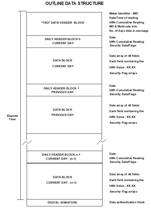
9.2.1 "TAG" Data Header Block

9.2.1.1 Meter Identifier-MID
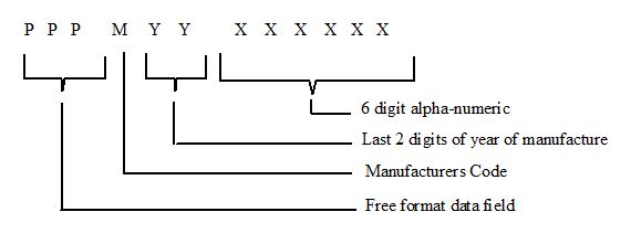
Character Mapping

complex image of process

Field

Character

Type

Range

Field Padding

Allowed Case

PPP

P

Alpha-numeric

A-Z, 0-9

Leading Zeroes

Upper or Lower Case

M

M

Alpha

A-Z

-

Upper Case Only

YY

Y

Numeric

0-9

-

-

XXXXXX

X

Alpha-numeric

A-Z, 0-9

Leading Zeroes

Upper Case Only

9.2.1.2 Date and Time of Reading of Meter

complex image of process

9.2.1.3 kWh Cumulative Reading

The absolute value of the cumulative meter register at the time of the interrogation. Expressed as :- 6 digit integer kWh value, padded with leading zeroes where appropriate.

1

2

3

4

5

6

Hundred Thousand

Ten Thousand

Thousands

Hundreds

Tens

Units

9.2.1.4 Maximum Demands - MDs

MD register data block consisting of 6 digit (4 integer and two decimal places) kW values with an implied decimal place, padded with leading zeroes where appropriate.

i) MD in kW in current charging period

ii) MD in kW in previous charging period

iii) Cumulative Maximum Demand

Register ID

1000's

100's

Tens

Units

1/10ths

1/100ths

Current kW MD

1

2

3

4

5

6

Previous kW MD

1

2

3

4

5

6

Cumulative MD

1

2

3

4

5

6

9.2.1.5 Date of Last MD Reset

Date of the last MD reset consisting of :-

complex image of process

9.2.1.6 Number of Maximum Demand Resets

The numerical value representing the number of Maximum Demand Resets, maximum value NN = 99.

No. of MD Resets

N

N

9.2.1.7 Multi-rate Energy Registers

Multi-rate energy registers at time of data read out consisting of 6 digit integer kWh values, padded with leading zeroes where appropriate.

Register ID

100k's

10k's

1000's

100's

Tens

Units

Rate 1

1

2

3

4

5

6

Rate 2

1

2

3

4

5

6

Rate 3

1

2

3

4

5

6

Rate 4

1

2

3

4

5

6

Rate 5

1

2

3

4

5

6

Rate 6

1

2

3

4

5

6

Rate 7

1

2

3

4

5

6

Rate 8

1

2

3

4

5

6

This data block should always be of the same size.

All data items should be transmitted, even if never initialised or used:

e.g. MD register on single phase meter, 8 rate register block even if 4 rate single phase meter, or if rate currently inactive;

e.g. due to tariff change.

9.2.1.8 Number of Days Data in Message

The numerical value representing the number of days of data to be transmitted by the outstation in response to a request for a data output.

No. of days of data in message

N

N

N

9.2.2 Daily Header Block

9.2.2.1 Day Identifier

Day identifier for the 24 hour period to which the 30 minute data relates.

complex image of process

9.2.2.2 Start of Day kWh Cumulative Reading

The absolute value of the cumulative meter (channel) register at 00:00 hours, at the start of the 24 hour period, to which the 48 periods of information relate.

Expressed as :- 8 digit decawatt hour value, padded with leading zeroes where appropriate.

1

2

3

4

5

6

7

8

Hundred Thousand

Ten Thousand

Thousands

Hundreds

Tens

Units

Tenths

Hundredths

9.2.2.3 Security Data and Flags

The normal status of each flag is logic zero and the presence or occurrence of an identified event is signalled by setting the flag to logic 1.

i) NNN - No. of successful level 2 accesses (maximum count = 7);

ii) BM - Battery Maintenance Flag;

iii) CF - Clock Failure;

iv) MD - MD reset flag, set for the day on which the MD was reset; and

v) PO - 24 hour continuous power outage of the outstation.

The security data and flags shall be coded into a single byte as follows:

Bit

7

6

5

4

3

2

1

0

Type

-

PO

MD

CF

BM

N

N

N

(Bit 7 is reserved for future use).

9.2.3 Data Block

The truncated absolute value of the cumulative meter (channel) register at the end of the 30 minute period, to which the value relates. Expressed as :- 4 digit kWh value, comprising two integers and two decimal digits, with an implied decimal place.

1

2

3

4

Tens

Units

Tenths

Hundredths

Appended for each 30 minute record are three security flags:

i) Reverse running indication;

ii) Successful level 2 password access; and

iii) Power Failure.

The normal status of these flags is logic zero and the presence or occurrence of an identified event is signalled by setting the flag to logic 1.

The data block will consist of a contiguous data array of 48, 4 digit values representing the value (truncated kWh cumulative register) for each respective demand period of the day e.g.

2220 2221 2222 2223 2224 2225 2226 2227

2228 2229 2230 2231 2232 2233 2234 2235

2236 2237 2238 2239 2240 2241 2242 2243

2244 2245 2246 2247 2248 2249 2250 2252

2252 2253 2254 2255 2256 2257 2258 2259

2260 2262 2262 2263 2264 2265 2266 2267

The data flags shall be presented as individual bit arrays with a flag for each demand period of the day in the array (48 bits per day). The sequence and location of individual bits within the data flag array corresponds directly to the demand period number of the respective 30 minute data value. i.e. bit 1 associated with demand period 1 (00:00 to 00:30) bit 48 associated with demand period 48 (23:30 to 24:00).

Data that has not yet been generated for the individual 30 minute demand periods i.e. in current day block for times following the time of data readout, shall be represented by FFFF. All flags for these associated periods shall be set to logic 0.

9.2.4 Data Authenticator

The data authenticator is appended to each data block associated with every data read process. The data authenticator is detailed in Appendix 3.

10. Appendix 2: Data Definitions and Descriptions

10.1 Data Block

10.1.1 General Definition

Complete set of data for one communications session

10.1.2 Data Definition

Identifier ::= NamedVariableList

{

variable list name 0

scope of access VDE-specific

scope may change FALSE

life time VDE

list of named variables 8, 16, 24, 32, 40, 48, 56, 64, 72, 80, 88

}

10.2 Meter Identifier - MID

10.2.1 General Definition

12 characters representing the Meter Identifier - MID

10.2.2 Data Definition

Identifier ::= NamedVariableObject

{

variable name 8

scope of access VDE-specific

scope may change FALSE

life time VDE

type description visible-string(SIZE(12))

read-write flag READ-ONLY

available TRUE

}

10.3 Date and Time of Reading Meter

10.3.1 General Definition

12 characters representing the date and time

10.3.2 Data Definition

DateAndTime ::= NamedVariableObject

{

variable name 16

scope of access VDE-specific

scope may change FALSE

life time VDE

type description numeric-string(SIZE(12))

read-write flag READ-ONLY

available TRUE

}

10.4 kWh Cumulative Reading

10.4.1 General Definition

6 characters representing the total cumulative kWh in kWh

10.4.2 Data Definition

CumulativekWh ::= NamedVariableObject

{

variable name 24

scope of access VDE-specific

scope may change FALSE

life time VDE

type description numeric-string(SIZE(6))

read-write flag READ-ONLY

available TRUE

}

10.5 Current kW Maximum Demand

10.5.1 General Definition

6 characters representing the current kW MD in 1/100s of a kW.

10.5.2 Data Definition

CurrentkWMD ::= NamedVariableObject

{

variable name 32

scope of access VDE-specific

scope may change FALSE

life time VDE

type description numeric-string(SIZE(6))

read-write flag READ-ONLY

available TRUE

}

10.6 Previous kW Maximum Demand

10.6.1 General Definition

6 characters representing the previous kW MD in 1/100s of a kW.

10.6.2 Data Definition

PreviouskWMD ::= NamedVariableObject

{

variable name 40

scope of access VDE-specific

scope may change FALSE

life time VDE

type description numeric-string(SIZE(6))

read-write flag READ-ONLY

available TRUE

}

10.7 Cumulative Maximum Demand

10.7.1 General Definition

6 characters representing the cumulative MD in 1/100s of a kW.

10.7.2 Data Definition

CumulativeMD ::= NamedVariableObject

{

variable name 48

scope of access VDE-specific

scope may change FALSE

life time VDE

type description numeric-string(SIZE(6))

read-write flag READ-ONLY

available TRUE

}

10.8 Date Of Last MD Reset

10.8.1 General Definition

6 characters representing the date of the last maximum demand reset.

10.8.2 Data Definition

MDResetDate :: = NamedVariableObject

{

variable name 56

scope of access VDE-specific

scope may change FALSE

life time VDE

type description numeric-string(SIZE(6))

read-write flag READ-ONLY

available TRUE

}

10.9 Number Of Maximum Demand Resets

10.9.1 General Definition

2 characters representing the number of maximum demand resets, 00 - 99.

10.9.2 Data Definition

NumMaxDemandResets :: = NamedVariableObject

{

variable name 64

scope of access VDE-specific

scope may change FALSE

life time VDE

type description numeric-string(SIZE(2))

read-write flag READ-ONLY

available TRUE

}

10.10 Multi-rate Energy Registers

10.10.1 General Definition

Eight registers containing the multi-rate kWh energy in kWh.

10.10.2 Data Definition

MultiRatekWh ::= NamedVariableObject

{

variable name 72

scope of access VDE-specific

scope may change FALSE

life time VDE

type description compact-array(SIZE(8)) OF

numeric-string(SIZE(6))

read-write flag READ-ONLY

available TRUE

}

10.11 Number of Days Data in Message

10.11.1 General Definition

Three characters representing the number of days of data to be transmitted.

10.11.2 Data Definition

NumberOfDays ::= NamedVariableObject

{

variable name 80

scope of access VDE-specific

scope may change FALSE

life time VDE

type description numeric-string(SIZE(3))

read-write flag READ-ONLY

available TRUE

}

10.12 Profile Data

10.12.1 General Definition

Daily data block comprising header data and profile data.

10.12.2 Data Definition

DailyData ::= NamedVariableObject

{

variable name 88

scope of access VDE-specific

scope may change FALSE

life time VDE

type description array OF DailyDataType SIZE(N)

read-write flag READ-ONLY

available TRUE

}

Where N = 20, 100, 250 or 450

DailyDataType :: = structure

{

DayIdentifier numeric-string(SIZE(6))

StartCumulativekWh numeric-string(SIZE(8))

DailyFlags bit-string(SIZE(8))

HalfHourData compact-array(SIZE(48)) OF

numeric-string (SIZE(4))

ReverseRunning bit-string(SIZE(48))

Level2 bit-string(SIZE(48))

PowerFail bit-string(SIZE(48))

}

10.13 Authenticator

10.13.1 General Definition

Eight byte string calculated using an authentication algorithm, an internal 8 byte authentication key and the preceding data.

10.13.2 Data Definition

Authenticator ::= NamedVariableObject

{

variable name 96

scope of access VDE-specific

scope may change FALSE

life time VDE

type description octet-string(SIZE(8))

read-write flag READ-ONLY

available TRUE

}

10.14 Authentication Key

10.14.1 General Definition

Eight byte string used by the authentication algorithm when calculating the authenticator.

10.14.2 Data Definition

AuthenticationKey ::= NamedVariableObject

{

variable name 104

scope of access VAA-specific

VAA name 39 -- VAAManagement

scope may change FALSE

life time VDE

type description octet-string(SIZE(8))

read-write flag WRITE-ONLY

available TRUE

}

10.15 Password

10.15.1 General Definition

Password means string of characters of length 6 characters, where each character is a case insensitive or sensitive alpha character (A to Z), a digit (0 to 9), the underscore character (_) or a hexadecimal passwords, (0 to F). The characters of a hexadecimal password must be in upper case.

10.15.2 Data Definition

Level2Password ::= NamedVariableObject

{

variable name 112

scope of access VAA-specific

VAA name 39 -- VAAManagement

scope may change FALSE

life time VDE

type description visible-string(SIZE(6))

read-write flag WRITE-ONLY

available TRUE

}

10.16 Date and Time Set

10.16.1 General Definition

12 characters representing the date and time

10.16.2 Data Definition

DateAndTimeSet ::= NamedVariableObject

{

variable name 120

scope of access VAA-specific

VAA name 39 -- VAAManagement

scope may change FALSE

life time VDE

type description numeric-string(SIZE(12))

read-write flag READ-WRITE

available TRUE

}

10.17 Time Adjust

10.17.1 General Definition

Signed integer representing the number of seconds by which to adjust the time. The maximum permissible value is ± 900 seconds.

10.17.2 Data Definition

DateAndTimeSet ::= NamedVariableObject

{

variable name 128

scope of access VAA-specific

VAA name 39 -- VAAManagement

scope may change FALSE

life time VDE

type description integer16

read-write flag WRITE-ONLY

available TRUE

}

10.18 Maximum Demand Reset

10.18.1 General Definition

Boolean which when written to will initiate a maximum demand reset.

10.18.2 Data Definition

MDReset ::= NamedVariableObject

{

variable name 136

scope of access VAA-specific

VAA name 39 -- VAAManagement

scope may change FALSE

life time VDE

type description integer8

read-write flag WRITE-ONLY

available TRUE

}

10.19 Free Format Field of Meter ID

10.19.1 General Definition

3 characters representing the free format field section of the Meter Identifier.

10.19.2 Data Definition

Identifier ::= NamedVariableObject

{

variable name 144

scope of access VAA-specific

VAA name 39 -- VAAManagement

scope may change FALSE

life time VDE

type description visible-string(SIZE(3))

read-write flag READ-WRITE

available TRUE

}

11. Appendix 3: Authentication

11.1 Authentication Overview

The purpose of authentication is to ensure that the receiver of the information can be confident that the contents of the message have not been altered since it left the sender and that the identity of the sender is not misrepresented.

The data authentication process uses a system whereby an Authentication Key will be loaded into Outstations by authorised parties. This Authentication Key will then be used to form an Authenticator on all the data to be communicated. The same Authentication Key will be provided to the authenticating parties. This will ensure that all authorised holders of the Authentication Key will be able to validate the authenticity of the information being transferred, provided of course that they also have knowledge of the Authentication Algorithm and its method of use.

The Authentication Key programmed into outstations and other validation equipment can be changed should the authentication system be compromised by disclosure or discovery of the key.

A Key Management System is required to ensure secure creation, storage and distribution of the Authentication Key to all parties concerned. This system is outside the scope of this document.

Different Authentication Keys may be used for various outstations or groups of Outstations if required. However, this will require a more complex Key Management System to be used, and knowledge of a number of Authentication Keys from which the appropriate one must be selected, by the authenticating party.

The description of the authentication process that follows is that to be used for data extracted from a Code of Practice Six meter via a BS EN61107 (FLAG) port. Other authentication procedures may be used for Code of Practice Seven systems providing they meet the requirements for authentication as specified in Code of Practice Seven.

11.2 Authentication Process

The complete Data Block described in Appendix 1(a) will be signed by an Authenticator to provide authentication of the source and validation of the data. This allows the content of the message to be sent in plain text and still to be validated and authenticated by authorised parties only.

There are four elements used in the calculation of the Authenticator. These are:

a) The Authentication Key

b) The Authentication Algorithm,

c) The Data Block,

d) The method by which (a) and (b) above operate on the contents of the Data Block to create the Authenticator.

The Authentication Key is an 8 byte binary number (56 bits of key data and 8 bits of parity) that is kept secret. It is placed only in those devices that need either to generate an Authenticator, or to check that the Authenticator received is valid.

The Algorithm used in the calculation of the Authenticator is the Data Encryption Standard (DES). This is a publicly available secret key block encryption algorithm, detailed in the following Standard: ANSI X3.92-1981.

The Data Block for authentication is detailed in Appendix 1(a). All the data in the total Data Block, consisting of the data in the Tag Header Block and the data for each of the days of daily data transmitted, are included in the Authenticator calculation. A change to any item of data in the Data Block affects the Authenticator.

The method by which the Authenticator is calculated, (using the Authentication Key, DES, and the data in the Data Block) is detailed in a controlled document, available on request to authorised parties from the Balancing and Settlement Code of Great Britain. However, the security of Authentication depends essentially on the security of the key, not on the security of the controlled document.

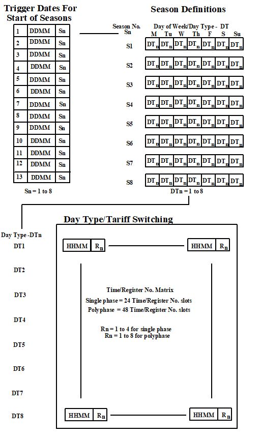
12. Appendix 4: Multi-rate Register Switching Regime

Multi-rate registers shall be programmable to provide the following minimum seasonal time of use tariff switching regime as described below and in the following diagrams;

    • A minimum of 24 stored register switching times for a single phase and 48 for polyphase Meter systems at any one time.

    • A minimum of 8 day types, each of which has an individual set of register switching times.

    • A sequential day of the week number to allow register switching to take place on any day of the week or combinations of days of the week. Monday shall be day 1.

    • A minimum of 8 seasons. Different weekday or combinations of weekdays register switching time registers can apply to each season.

    • In addition to switching times a minimum of 13 MD Reset dates, commencing at the start of the settlement day, for the start of the seasons.

    • A minimum of 2 daylight clock time changes, indicated by date and month during which a time shift of 1 or 2 hours will be implemented at 02:00 (time advance) or 03:00 (time retard). This shall not affect the UTC clock.

    • A minimum of 12 exclusion dates during which any day’s register switching times, indicated by day type, can be implemented for each exclusion date.

    • Where Maximum Demand (MD) metering is being operated the MD shall be programmable to reset automatically as defined by 13 MD reset dates.

Where load switching is provided it shall comply with the appropriate standards.

complex image of process

Exclusion Dates

Date of MD Reset

1

DDMM

DT

1

DDMM

2

DDMM

DT

2

DDMM

3

DDMM

DT

3

DDMM

4

DDMM

DT

4

DDMM

5

DDMM

DT

5

DDMM

6

DDMM

DT

6

DDMM

7

DDMM

DT

7

DDMM

8

DDMM

DT

8

DDMM

9

DDMM

DT

9

DDMM

10

DDMM

DT

10

DDMM

11

DDMM

DT

11

DDMM

12

DDMM

DT

12

DDMM

13

DDMM

Daylight Saving Clock Changes

DDMM

+H

Advance Tariff Clock at 2:00am by ‘H’ hours on date specified

DDMM

-H

Retard Tariff Clock at 3:00am by ‘H’ hours on date specified

Note - Valid range of ‘H’ is either 1 or 2.

13. Appendix 5: Phase Failure Indication

13.1 Notes of Guidance

Modern electronic Meters are Approved by Ofgem as “Polyphase Multi-configurable” meters and can be installed on a wide variety of voltage supply arrangements. Although the Half Hourly market is dominated by the 3 phase and neutral symmetrical (120) supply, there are many other low voltage configurations, including 2 phase and neutral symmetrical (120) supply, 2 phase and neutral (180) supply and the single phase and neutral supply.

These Notes of Guidance are intended for the use of Meter Operators and the Data Collectors. To eliminate the problems caused by the incorrect recording of ‘Phase Failure Indication’ where Polyphase Multi-configurable electronic Meters are installed on single and 2 phase supplies.

13.2 Solution

The preferred solution is to energise the remaining measuring elements on the Meter with a voltage supply from one of the existing phases. This can normally be achieved by the installation of a second conductor appropriately fused from the top of the cut-out to the idle measuring element/s input terminal on the Meter. The output terminal should be safely and securely insulated with a blind terminator to prevent electric shock or unauthorised access. The cross sectional area and insulation of the conductor used for the idle measuring element should satisfy any safety requirements or Regulations in respect of fault levels and insulation.

The installation should be clearly marked with phase colours or numbers and labelled to indicate the unusual wiring arrangements.

1Code Effective Date” means the date of the Framework Agreement.