Advanced Search

Code of Practice 8: The Metering of Import Active Energy via Low Voltage Circuits for Non-Half Hourly Settlement Purposes

v 8.0
Download

Balancing and Settlement Code

CODE OF PRACTICE EIGHT

CODE OF PRACTICE FOR THE METERING OF IMPORT ACTIVE ENERGY VIA LOW VOLTAGE CIRCUITS FOR NON-HALF HOURLY SETTLEMENT PURPOSES

Issue 1

Version 8.0

DATE: 29 June 2023

Code of Practice Eight

CODE OF PRACTICE FOR THE METERING OF IMPORT ACTIVE ENERGY VIA LOW VOLTAGE CIRCUITS FOR NON-HALF HOURLY SETTLEMENT PURPOSES

1. Reference is made to the Balancing and Settlement Code for the Electricity Industry in Great Britain and, in particular, to the definition of "Code of Practice" in Annex X.1 thereof.

2. This is Code of Practice Eight, Issue 1, Version 8.0.

3. This Code of Practice shall apply to Metering Systems comprising Metering Equipment that is subject to the requirements of Section L of the Balancing and Settlement Code.

4. This Code of Practice is effective from 29 June 2023.

5. This Code of Practice has been approved by the Panel.

Intellectual Property Rights, Copyright and Disclaimer

The copyright and other intellectual property rights in this document are vested in Elexon or appear with the consent of the copyright owner. These materials are made available for you for the purposes of your participation in the electricity industry. If you have an interest in the electricity industry, you may view, download, copy, distribute, modify, transmit, publish, sell or create derivative works (in whatever format) from this document or in other cases use for personal academic or other non-commercial purposes. All copyright and other proprietary notices contained in the document must be retained on any copy you make.

All other rights of the copyright owner not expressly dealt with above are reserved.

No representation, warranty or guarantee is made that the information in this document is accurate or complete. While care is taken in the collection and provision of this information, Elexon Limited shall not be liable for any errors, omissions, misstatements or mistakes in any information or damages resulting from the use of this information or action taken in reliance on it.

AMENDMENT RECORD

This Code of Practice defines the minimum requirements for directly connected and transformer operated Metering Equipment at the Defined Metering Point for the measurement of Import Active Energy via low voltage circuits for Non-Half Hourly Settlement purposes.

BSCCo shall retain copies of, inter alia, the Code of Practice together with copies of all documents referred to in them, in accordance with the provisions of the Balancing and Settlement Code (the Code).

1. SCOPE

This Code of Practice states the practices that shall be employed and the facilities that shall be provided for the measurement and recording of the quantities required for Settlement purposes.

This Code of Practice specifically applies to directly connected and transformer operated Metering Equipment to be installed FOR THE METERING OF IMPORT ACTIVE ENERGY VIA LOW VOLTAGE CIRCUITS FOR NON-HALF HOURLY SETTLEMENT PURPOSES.

This Code of Practice only applies to "whole current" and transformer operated Metering Equipment for Import Active Energy measured in kWh. No provision is made for the measurement of Reactive or Apparent Energy or any Maximum Demand.

This Code of Practice defines the extent of Metering Equipment to be installed by a SVA Meter Operator Agent in fulfilling its role in the provision of equipment and data for Non-Half Hourly Settlement purposes.

This Code of Practice derives force from the Balancing and Settlement Code, and in particular the metering provisions contained in Section L, to which reference should be made. It should also be read in conjunction with the relevant BSC Procedures.

Metering Equipment that meets the requirements of this Code of Practice is not applicable where a Registrant is required by its Supply Licence (and as referenced in Section L3.2.6) to install Metering Equipment that is capable of providing measured electricity consumption data for multiple periods (at least half hourly) and providing the Registrant with remote access to such data.

This Code of Practice does not contain the calibration, testing and commissioning requirements for Metering Equipment used for Settlement purposes. These requirements are detailed in Code of Practice Four1 - "Code of Practice for Calibration, Testing and Commissioning Requirements for Metering Equipment for Settlement Purposes".

Any device that is not covered by SI1679 shall not be involved in deriving the kWh value for Settlement purposes. To clarify, an integral Outstation may be used but a remote outstation (peripheral device) that derives a kWh value (e.g. via pulsed outputs) shall not be used. A remote outstation that transfers the kWh value of the primary register in accordance with the manufacturers protocol may be used.

Dispensations from the requirements of this Code of Practice may be sought in accordance with the Balancing and Settlement Code and BSCP32.

In the event of an inconsistency between the provisions of this Code of Practice and the Balancing and Settlement Code, the provisions of the Balancing and Settlement Code shall prevail.

Meters manufactured prior to 1 April 2003 that have been tested and received type approval by the Authority (Ofgem or its predecessors) to a standard not less than Class 2 applicable at the time of type approval shall be deemed compliant with this Code of Practice.

2. REFERENCES

The following documents are referred to in the text:-

BS EN 61036

‘AC Static Watthour Meters for Active Energy (Classes 1 and 2)’

BS EN 60521

Class 0.5, 1 and 2 Alternating Current Watt-Hour Meters.’

BS 7856

Code of Practice for Design of Alternating Current Watt-Hour Meters for Active Energy (Classes 1 and 2)’

BS 7951:2000

‘Electricity Meters. Alternating current single phase watt-hour Telemeters of accuracy class 1 or 2.’

BS EN 60044-1:1999

‘Instrument Transformers – Part 1: Current Transformers’

Balancing and Settlement Code

‘Section X; Annex X-1 and Sections L and S’

BSC Procedures List

‘See BSC Section H 1.3.2 (a) – Code Subsidiary Documents’

Code of Practice Four

Code of Practice for Calibration, Testing and Commissioning Requirements for Metering Equipment for Settlement Purposes’

Electricity Act 1989

‘Schedule 7, as amended by Schedule 1, to the Competition and Services (Utilities) Act 1992.’

Statutory Instrument 2002 No. 2665

‘The Electricity Safety, Quality and Continuity Regulations 2002’

Meter Operation Code of Practice Agreement2

‘Agreement between Meter Operators and Distribution Businesses governing arrangements for safety and technical competence in accordance with the Retail Energy Code

International Telecommunication Union - RTF.460 (ISBN92-61-05311-4)

‘Standard Frequency and Time Signal Emission’

Statutory Instrument 1998 No.1566

‘Electricity – The Meters (Certification) Regulations 1998.’

TPRD/L/3297/R88

‘Specification for Radio Teleswitches for tariff and load control’

Utilities Act 2000

‘Utilities Act 2000’

Statutory Instrument 2006 No.1679

The Measuring Instruments (Active Electrical Energy meters) Regulations 2006 (SI 2006/1679)

3. DEFINITIONS AND INTERPRETATIONS

Save as otherwise expressly provided herein, words and expressions used in this Code of Practice shall have the meanings attributed to them in the Balancing and Settlement Code and are included for the purpose of clarification.

Note: * indicates definitions in the Balancing and Settlement Code.

Note: † indicates definitions which supplement or complement those in the Balancing and Settlement Code.

Note: ‡ indicates definitions specific to this Code of Practice

3.1 Active Energy *

Active Energy means the electrical energy produced, flowing or supplied by an electric circuit during a time interval, being the integral with respect to time of the instantaneous Active Power, measured in units of watt-hours or standard multiples thereof.

3.2 Active Power *

Active Power means the product of voltage and the in-phase component of alternating current measured in units of watts and standard multiples thereof, that is:-

1,000 Watts = 1 kW

1,000 kW = 1 MW

3.3 Actual Metering Point

Actual Metering Point means the physical location at which electricity is metered.

3.4 Certified ‡

Certified means a meter conforming with the Statutory Instrument, 1998 No.1566 “Electricity – The Meters (Certification) Regulations”.

3.5 Current Transformer ‡

A transformer for use with electrical measuring instruments, electrical protection and/or control equipment, for the transformation of current and in which the current in the secondary winding, in normal conditions of use, is substantially proportional to the current in the primary winding and different from it by an angle which approaches zero for an appropriate direction of the connections.

3.6 De-Energised ‡

De-Energised means the temporary removal of the supply at a Defined Metering Point (e.g. the main circuit connections to the Public Distribution System Operator’s network are still made) such that all or part of the Metering Equipment is considered to be temporarily "inactive" for the purposes of Settlement. e.g. unoccupied premises where the incoming switchgear has been opened or the cut-out fuse(s) removed.

3.7 Defined Metering Point

Defined Metering Point means the physical location at which the overall accuracy requirements as stated in this Code of Practice are to be met. The Defined Metering Points are identified in section 8.

3.8 Distribution System *

(i) any Public Distribution System; and

(ii) any other distribution system in Great Britain for which the condition is satisfied that all entry/exit points are subject to registration in SMRS pursuant to the provisions of the Retail Energy Code; where:

(1) 'distribution system' has the meaning given or to be given to that term in section 4(4) of the Act, following amendment of the Act by section 28 of the Utilities Act 2000;

(2) 'entry/exit point' means a point at which electricity may flow on to or off such distribution system other than from or to the Transmission System or another such system or a Public Distribution System.

3.9 electricity *

electricity means Active Energy and Reactive Energy.

3.10 Import

Import means, for the purposes of this Code of Practice, an electricity flow away from the Transmission System. (i.e. At a Customer’s premises, a power flow towards the Customer’s installation.)

3.11 Isolating Switch ‡

means a switch located between a Meter and customer’s fuse box and providing a means of isolating the electricity supply to the customer’s fuse box and which may be operated by the customer or their electrical contractor.

3.12 Meter *

Meter means a device for measuring Active Energy and/or Reactive Energy.

3.13 Metering Equipment

Metering Equipment means Meters, Telemeters, Timeswitches, Radio Teleswitches, Isolating Switches, connector blocks, test terminal blocks, measurement transformers (voltage, current or combination units), metering protection equipment including alarms, circuitry, associated Communications Equipment and Outstation and wiring.

3.14 Meter Register ‡

Meter Register means a device, associated with a Meter, from which it is possible to obtain a reading of the amount of Active Energy that has been supplied by a circuit.

3.15 Radio Teleswitch ‡

means a timing device for tariff and load control purposes, utilising a time base derived from, and maintained by, a radio signal in accordance with specification TPRD/L/3297/R88.

3.16 Registrant *

Registrant means in relation to a Metering System, the person for the time being registered in CMRS or (as the case may be) SMRS in respect of that Metering System pursuant to Section K of the Balancing and Settlement Code.

3.17 SVA Customer *

means a person to whom electrical power is provided, whether or not that person is the provider of that electrical power; and where that electrical power is measured by a SVA Metering System.

3.18 Telemeter ‡

means a combined Meter and Radio Teleswitch.

3.19 Timeswitch ‡

means a timing device for tariff and load control purposes, utilising a time base derived from either mains frequency or an internal crystal controlled clock.

3.20 UTC ‡*

UTC means Co-ordinated Universal Time which bears the same meaning as in the document Standard Frequency and Time Signal Emission, International Telecommunication Union - RTF.460(ISBN92-61-05311-4) (colloquially referred to as Rugby Time).

4. MEASUREMENT CRITERIA – Directly connected (whole current) meters

4.1 Measured Quantities

4.1.1 Measured Quantities

For each separate circuit measurements of Import Active Energy in kWh are required for Settlement purposes.

Registers shall be provided in accordance with clause 6.3.1.

4.2 Accuracy Requirements

4.2.1 Type Test Requirements

Meters shall be type tested in accordance with and satisfy the requirements of BS EN 61036 or BS 7951:2000 or BS EN 60521 as appropriate.

4.2.2 Import Active Energy Accuracy Requirements

(i) Meter Accuracy

CONDITION

LIMIT OF ERRORS AT STATED

SYSTEM POWER FACTOR

Current

Power Factor

Limits of Error

100% Imax to 10% Ib inclusive

1

± 2.0%

4.2.3 Initial verification (calibration) – Authority (Ofgem) Certification

See Certification Directions, clause 7(2).

Where a supply is exempt from certification, in accordance with Section 2 of Schedule 7 of the Electricity Act 1989, the Meter shall undergo initial verification to a standard equivalent to that which would have been required by the Electricity Act had the Meter not been exempt.

4.2.4 In-service Accuracy limits

The overall accuracy of the energy measurements at, or referred to, the Defined Metering Point shall at all times be within the limits of error for in-service accuracy.

The overall in-service accuracy limits are +2.5% to –3.5% at any load at which the Metering Equipment is designed to operate.

5. MEASUREMENT CRITERIA – current transformer operated meters

5.1 Measured Quantities

5.1.1 Measured Quantities

For each separate circuit measurements of Import Active Energy in kWh are required for Settlement purposes.

Registers shall be provided in accordance with clause 6.3.1.

5.2 Accuracy Requirements

5.2.1 Type Test Requirements

Meters shall be type tested in accordance with and satisfy the requirements of BS EN 61036 or BS 7951:2000 or BS EN 60521 as appropriate.

5.2.2 Import Active Energy Accuracy Requirements

(i) Meter Accuracy

CONDITION

LIMIT OF ERRORS AT STATED

SYSTEM POWER FACTOR

Current

Power Factor

Limits of Error

100% Imax to 5% In inclusive

1

± 2.0%

5.2.3 Initial verification (calibration) – Authority (Ofgem) Certification

See Certification Directions, clause 7(2).

Where a supply is exempt from certification, in accordance with Section 2 of Schedule 7 of the Electricity Act 1989, the Meter shall undergo initial verification to a standard equivalent to that which would have been required by the Electricity Act had the Meter not been exempt.

5.2.4 In-service Accuracy limits

The overall accuracy of the energy measurements at, or referred to, the Defined Metering Point shall at all times be within the limits of error for in-service accuracy.

The overall in-service accuracy limits are +2.5% to –3.5% at any load at which the Metering Equipment is designed to operate.

5.2.5 Voltage supply for Current Transformer operated Meters

A separately fused voltage supply shall be provided between the cut-out and the Current Transformer operated Meter. No burden other than Metering Equipment shall be connected to the fused side of the voltage supply. The neutral conductor of the voltage supply to the Meter shall not be fused.

5.2.6 Access to voltage supply

Access to the voltage supply fuse(s) shall only be possible by the breaking of a seal.

5.2.7 Current Transformers installed on existing circuits

Where circuits, other than those newly installed, are to be metered to this Code of Practice and where the installed Current Transformers do not comply with the Class accuracies specified in clause 6.2.1, then such Current Transformers may be used providing the following requirements and those in clause 5.2.4 are met and that where subsequently an alteration to the Metering Equipment is carried out, new Current Transformer(s) shall be provided to meet the accuracy requirements specified in clause 6.2.1 below.

5.2.8 Access to Current Transformers

Access to both the primary and secondary sides of Current Transformers shall only be possible by the breaking of a seal. Where ‘open ring’ Current Transformers are used, measures shall be taken to prevent unauthorised access to the central aperture, such that no additional conductors may be passed through the aperture without the breaking of a seal.

6. METERING EQUIPMENT CRITERIA

Metering Equipment shall be accommodated in a clean and dry environment.

For each circuit, other than one which is de-energised, the voltage supply to any Meters and Displays shall be connected such that it is normally energised to facilitate reading of the Meter Register(s).

6.1 Meters

The Meters may be either static or induction disc types.

For each circuit, Import Active Energy Meters shall be supplied which shall meet the requirements of BS 7856 and either BS EN 61036 Class 2 or BS EN 60521 Class 2 or BS 7951:2000.

Import Active Energy Meters provided for the metering of supplies to Customers shall be in accordance with Schedule 7 of the Electricity Act 1989.

Import Active Energy Meters shall be configured such that the number of measuring elements is equal to or one less than the number of primary system conductors. These include the neutral conductor, and/or the earth conductor where system configurations enable the flow of zero sequence energy. The Meter and any Current Transformers shall be of a rating appropriate to the installation.

All programmable Meters shall have a security regime to minimise unauthorised access to data and configuration changes.

6.2 Current Transformers

The term "Current Transformer" used in Section 5 does not preclude the use of other measuring techniques with a performance equal to that specified for such measurement transformers.

For each circuit where a Current Transformer is used, it shall meet the requirements set out below.

Where required, one set of Current Transformers to BS EN 60044-1:1999 with a minimum standard of accuracy to Class 0.5 shall be provided per circuit. Preferably the Current Transformers shall be dedicated for Settlement purposes, but the Current Transformers may be used for other purposes provided the overall accuracy requirements in clause 5.2.4 are met.

The total burden on each Current Transformer shall not exceed the rated burden of such Current Transformer.

6.3 Registers, Displays and Facilities

6.3.1 Meters and Telemeters

Rate registers shall be provided for either:

(a) the total Import Active Energy measured by that Meter/Telemeter; or

(b) each rate measured by a multi-rate Import Active Energy Meter/Telemeter. The sum of such multi-rate registers shall be equal3 to the total Import Active Energy measured by that Meter/Telemeter.

6.3.2 Displays

The Metering Equipment shall display the Import Active Energy in kWh for each register utilised on the Meter (not necessarily simultaneously).

6.3.3 Timeswitches

Timeswitches, where required, shall be installed and the time set to the time standard (GMT or BST) as required by the Supplier’s tariff requirements.

6.3.4 Teleswitches

Teleswitches, where required, shall be installed and set to the appropriate Application/User/Group Code in accordance with the Supplier’s tariff requirements.

6.3.5 Time keeping accuracy

Timeswitches, where required, shall be installed and set as close as reasonably practical to the time standard (GMT or BST) as required by the Supplier’s tariff requirements. Timeswitches shall be maintained to an accuracy of ±2 hours.

7. Installation of Meters

7.1 Not Used

7.2 Meter Operation Code of Practice Agreement requirements

The Retail Energy Code Meter Operation Code of Practice Agreement covers the installation, operation and maintenance of Metering Equipment by Meter Operator Agents. It identifies the safety and technical requirements relevant to meter operation, and the interface between a Meter Operator Agent and a Distribution System Operator. It specifies the requirements for both the Metering Business and field staff as appropriate.

The principles within The Meter Operation Code of Practice Agreement form the basis of good practice for meter installation, operation and maintenance at any site that is connected, either to a Distribution System or to any other network.

A party's compliance with The Retail Energy Code Meter Operation Code of Practice Agreement is regulated and policed by the Registration Authority4.

7.3 Appropriate Seals

All SVA Customers Metering Equipment shall be sealed in accordance with of the Retail Energy Code Meter Operation Code of Practice Agreement and any applicable BSCP.

8. Defined metering points and point of supply

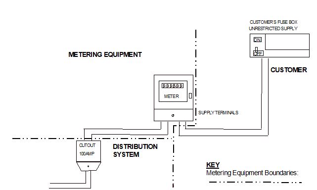
8.1 Single-rate Whole Current Meter – where the SVA Customer’s installation directly connects with the installed meter.

8.1.1 Distribution System Operator Responsibilities

The Distribution System Operator is responsible for the service cable and the cut-out.

8.1.2 Meter Operator Agent Responsibilities

The SVA Meter Operator Agent shall install the meter.

The conductors between the cut-out and the input terminals of the Meter shall be installed by, and be the responsibility of, the SVA Meter Operator Agent.

The conductors between the Meter’s outgoing terminals and the consumer unit will be part of the SVA Customer’s installation but the responsibility of the SVA Meter Operator Agent for connection.

Single-rate Whole Current Meter

complex image of process

Note:

The diagrams in this section of the Code of Practice are for example only. These diagrams should not be taken as definitive wiring diagrams for any installation.

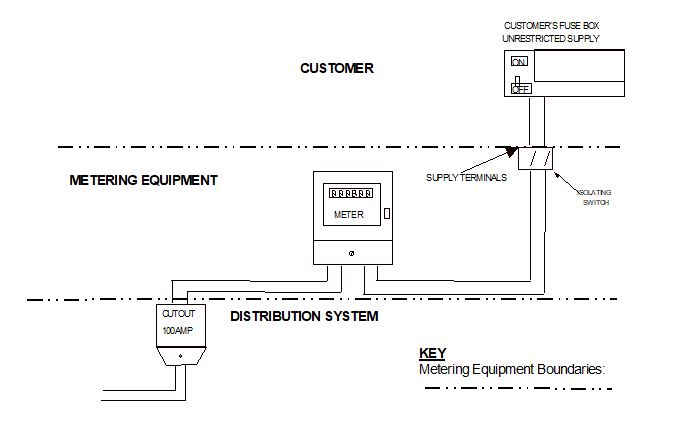
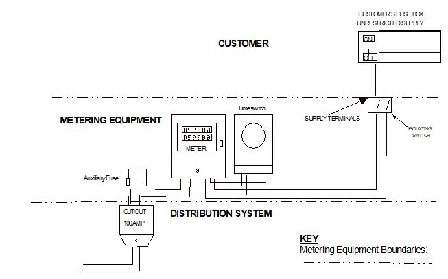
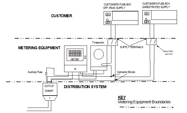
8.2 Single-rate or Multi-rate Whole Current Meter – where the SVA Customer’s installation does not directly connect with the installed meter(s).

8.2.1 Installations with an Isolating Switch

Where an installation has an additional meter, a timeswitch, teleswitch, or external isolating switch, then the SVA Meter Operator Agent will install these items. Also, the interconnecting wiring between the items up to the last item of equipment, for example an isolating switch or meter before the ‘consumer unit’, would be installed and maintained by the SVA Meter Operator Agent. However, any wiring between the final item of equipment and the ‘consumer unit’ would be part of the SVA Customer’s installation.

Single-rate Whole Current Meter with Isolating Switch

complex image of process

Note:

The diagrams in this section of the Code of Practice are for example only. These diagrams should not be taken as definitive wiring diagrams for any installation.

Multi-rate Whole Current Meter with Isolating Switch

complex image of process

Multi-rate Whole Current Meter with Isolating Switches and controlled Off-Peak Load

complex image of process

Note:

The diagrams in this section of the Code of Practice are for example only. These diagrams should not be taken as definitive wiring diagrams for any installation.

8.3 Other Requirements

8.3.1 Anti Fraud Devices

Where considered necessary by the Supplier, anti-fraud devices such as security blocks fitted between the cut-out and the meter, and plastic bubbles would be supplied and fitted by the SVA Meter Operator Agent.

8.3.2 Outside Meter Cabinets

An outside meter cabinet will normally be considered the SVA Customer's property and their responsibility to replace in the event of it being damaged.

8.3.3 High Risers and Laterals

Where the metering is situated within a communal metering area the risers are normally privately owned.

Where the metering is situated in the individual flats, then the ownership of the risers will have been determined at the time of connection, in conjunction with the Distribution System Operator.

8.4 Current Transformer Operated Metering Equipment

8.4.1 Provision of Test and Isolation facilities

For the purposes of meter connection by the SVA Meter Operator Agent, the Current Transformers, meter panel, associated multicore cable, test/isolating facilities and voltage fuses will be provided by the Distribution System Operator or a contractor nominated by the SVA Customer.

8.4.2 Interface between SVA Meter Operator Agent and Distribution System Operator

In normal circumstances the SVA Meter Operator Agent to Distribution System Operator interface point will be the outgoing connections from the test/isolating facilities and the metering panel voltage fuses.

8.4.3 SVA Customer cabling

The cabling from the Distributor System Operator’s cut-out or main fuse, through Current Transformers and into a SVA Customer’s main switch is the property of the SVA Customer. Where this cabling is provided by the SVA Customer or their contractor, then the cabling shall be to the Distribution System Operator’s specification.

Current Transformer Operated Metering Equipment

9. Provision of Metering Equipment

The table below is for guidance on the provision and responsibility of selected items in any particular installation.

The term Equipment Owner (EO) has been used to identify the party responsible for providing the item of Meter Equipment or associated / ancillary equipment.

Note:- Not all items in the following table will be present in all installations.

Table defining responsibilities for various items of Metering Equipment

Item

Provider of equipment

Field work Responsibility

(A) All installations

Service cable

DSO

DSO

High Risers and Laterals

EO or landlord

DSO

Cut-out

DSO

DSO

Main fuses (cut-out fuses)

DSO

DSO or SVA MOA*

Circuit Breaker (or equivalent) (for larger installations)

DSO

DSO or SVA MOA*

Meter / Telemeter

EO

SVA MOA

Timeswitch

EO

SVA MOA

Teleswitch

EO

SVA MOA

(B) Whole current installations

Cables: cut-out to meter

EO

SVA MOA

Cables: from meter to SVA Customer owned switchgear

SVA Customer/contractor

SVA MOA* to connect

Isolating switch

EO5

SVA MOA

Connector blocks

EO

SVA MOA

Cables: between meter and other EO supplied apparatus or between other items of EO supplied apparatus

EO

SVA MOA

Revenue Protection equipment

Supplier/EO

SVA MOA

Cables: between Revenue Protection equipment and other apparatus

Supplier/ EO

SVA MOA

(C) Current Transformer operated installations

Current Transformers

DSO

DSO

Meter panel

DSO

DSO

Test terminal block

DSO

DSO

Potential fuses at source

DSO

DSO

Potential fuses or isolators on meter panel

DSO

DSO

Additional potential fuses for meters or other apparatus

EO

SVA MOA

Multicore and all cabling between source and meter panel

DSO

DSO

Cables: beyond test terminal block and potential fuses

EO

SVA MOA

Cables: cut-out (or Circuit Breaker) to SVA Customer’s mainswitch

SVA Customer/contractor

SVA MOA* to connect

SVA MOA* means MOA may operate this equipment under the terms of Retail Energy Code Meter Operation Code of Practice Agreement.

Note: Use of the Table above in respect of ownership, provision, specification and ongoing maintenance of CT chambers, metering panels, isolating switches and rising mains should be confirmed with the relevant DSO. The Table illustrates the typical arrangements, but cannot be relied upon as being definitive in every circumstance.

1 The current Issue 5 of Code of Practice Four may require minor amendments to accommodate Non-Half Hourly Metering Systems.

2 The Meter Operation Code of Practice Agreement is an agreement between Distribution System Operators and Meter SVA Operator Agents in accordance with the Retail Energy Code

3 Allowance shall be made for fractions of kWh measured by each register, not being included in the total Import Active Energy calculation.

4 The Registration Authority is defined within Meter Operation Code of Practice.

5 Ownership may transfer from the Distribution System Operator to the SVA Customer.